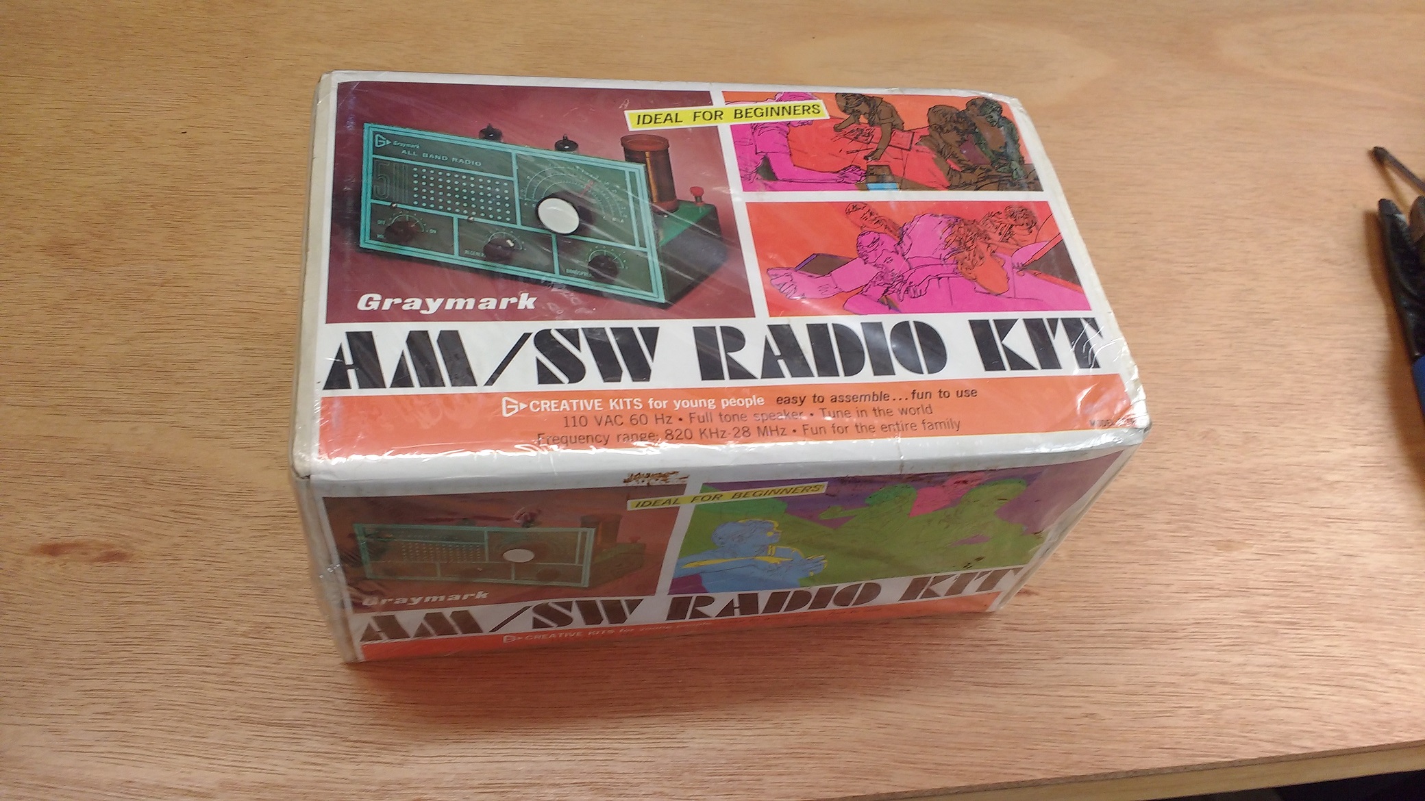
Graymark used colorful boxes for their kits to help make them attractive to 12 and 13 year-olds – KA2C – then WN3PKU – used one of these radios as his first receiver in 1970 as a novice for about 8 months of initial operations and contacts
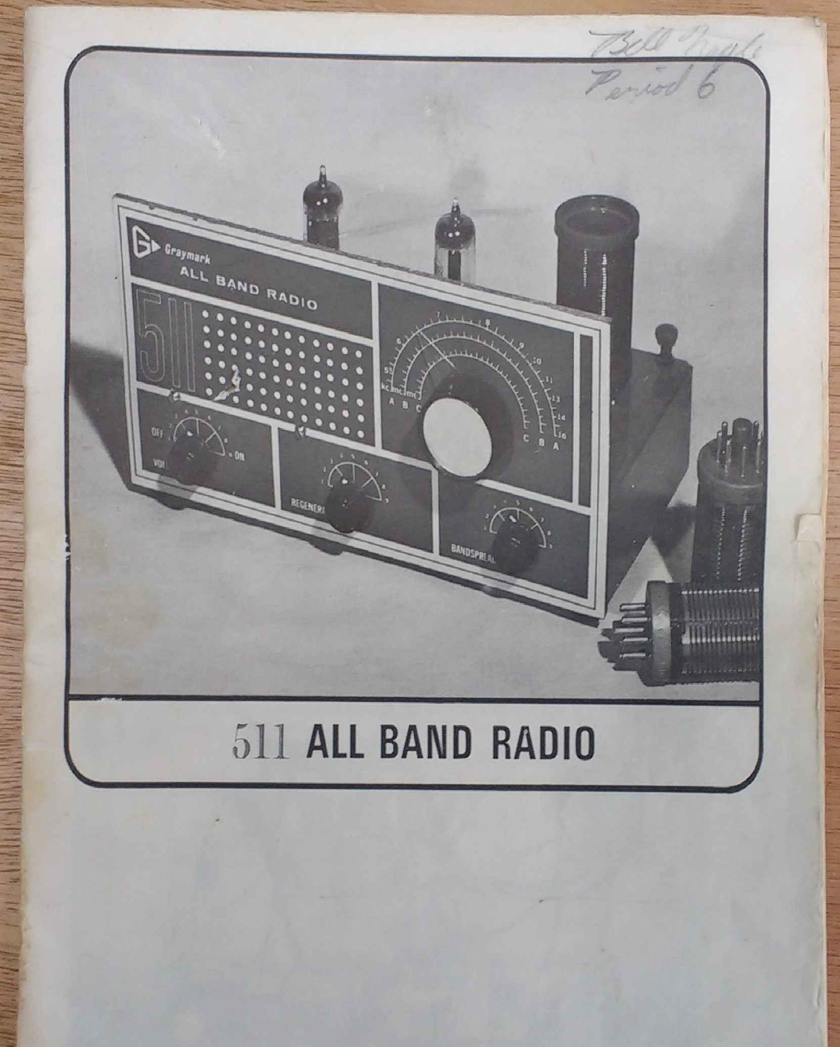
The Graymark 511 used just 3 tubes and had no power transformer – the AM broadcast band and 2 or 3 SW bands were supported using a different plug-in coil for each band which were wound by the student
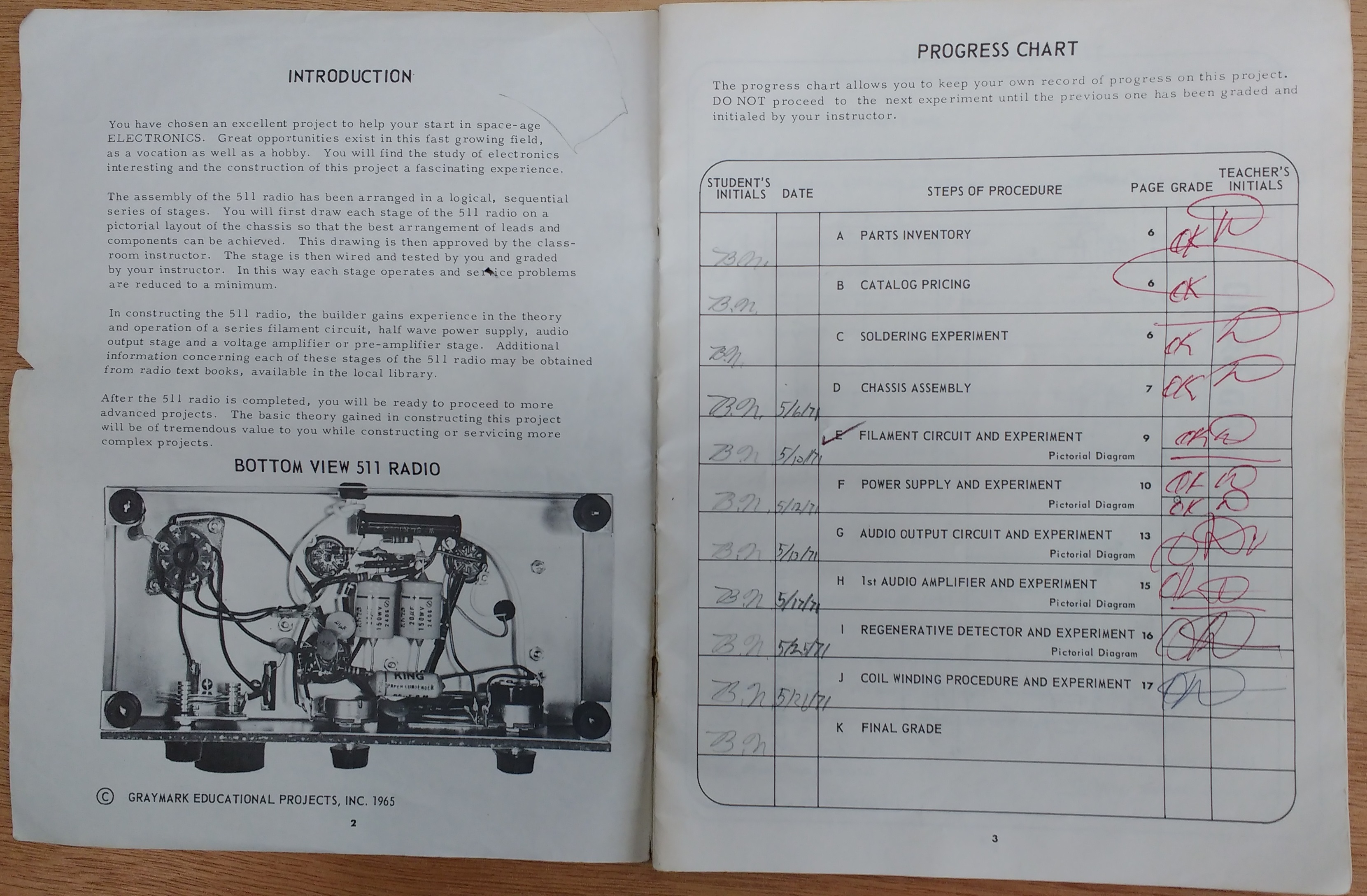
Construction was performed in about a dozen session by the student and checked by an instructor with documentation in the manual
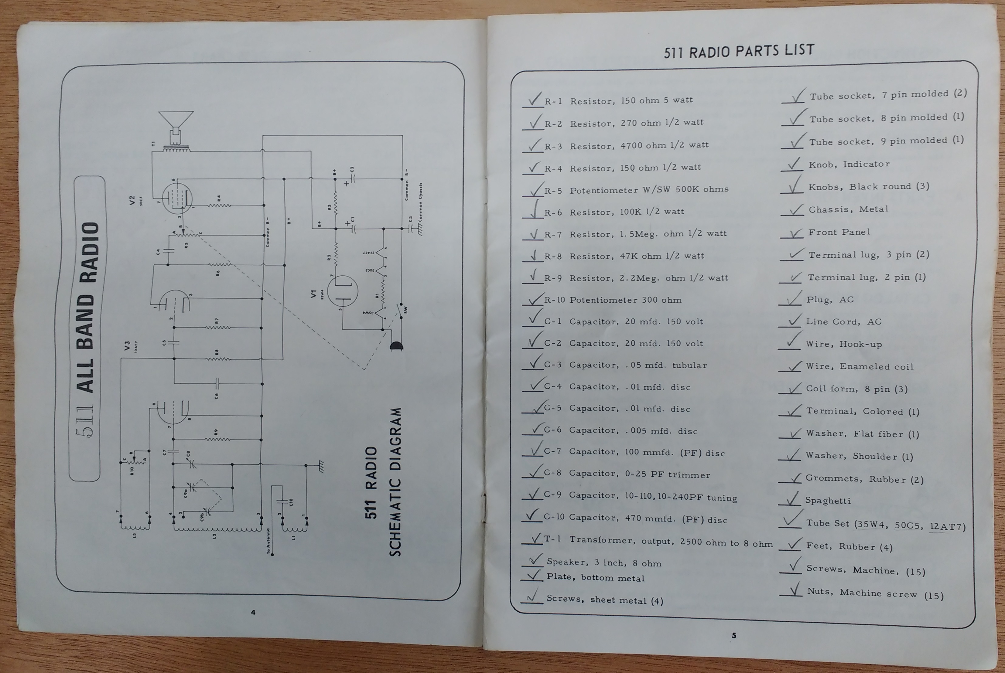
schematic and parts list

This diagram showed the wiring steps for the 511 radio and different test stages such as testing the filament circuit which wired 110 VAC directly the the 3 tube filaments in series and a power dropping resistor

Underside of the radio prior to restoration
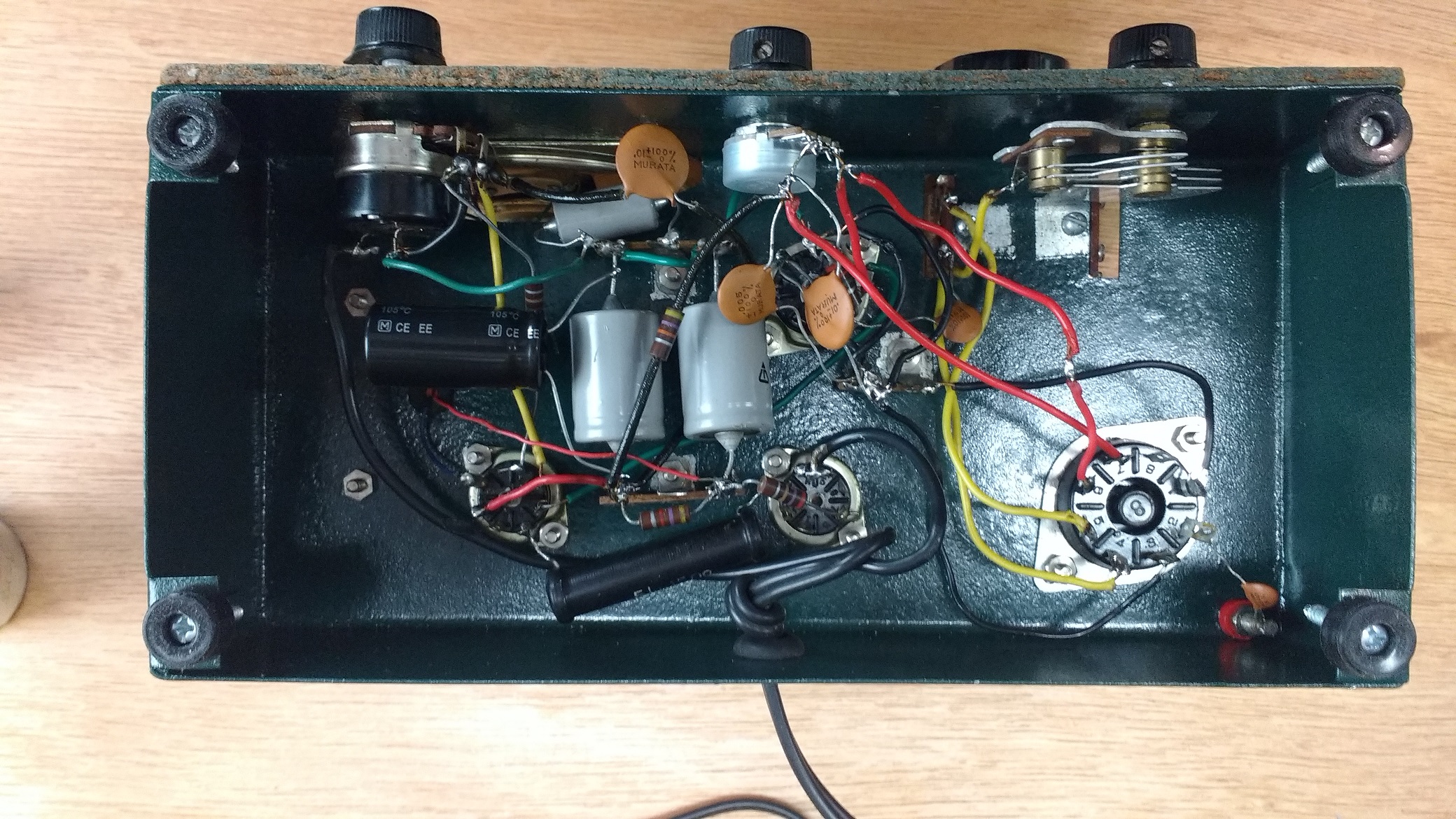
The chassis was completely stripped of components and naval jelly used with Q-tips to remove some rust spots – then the chassis was painted with a matching green metal paint using small pieces of masking tape to exclude grounding areas for terminal strips and other components – the regeneration potentiometer was bad and replaced with a similar modern component – the antenna binding post was missing and replaced – an additional B+ filter capacitor was added to the circuit to reduce hum – rubber feet were added to the chassis
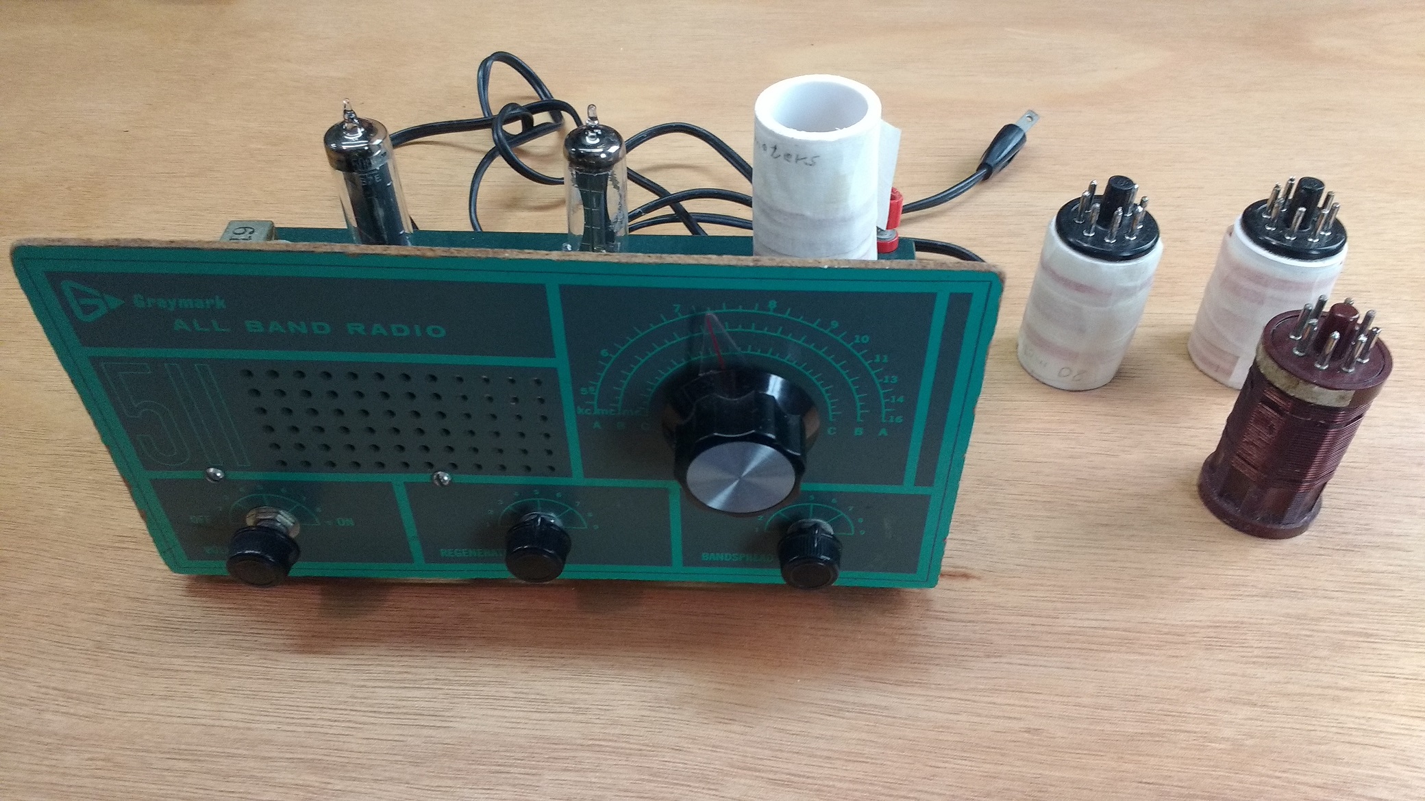
The main tuning dial was broken – the pointer was glued to a new and slightly different tuning knob
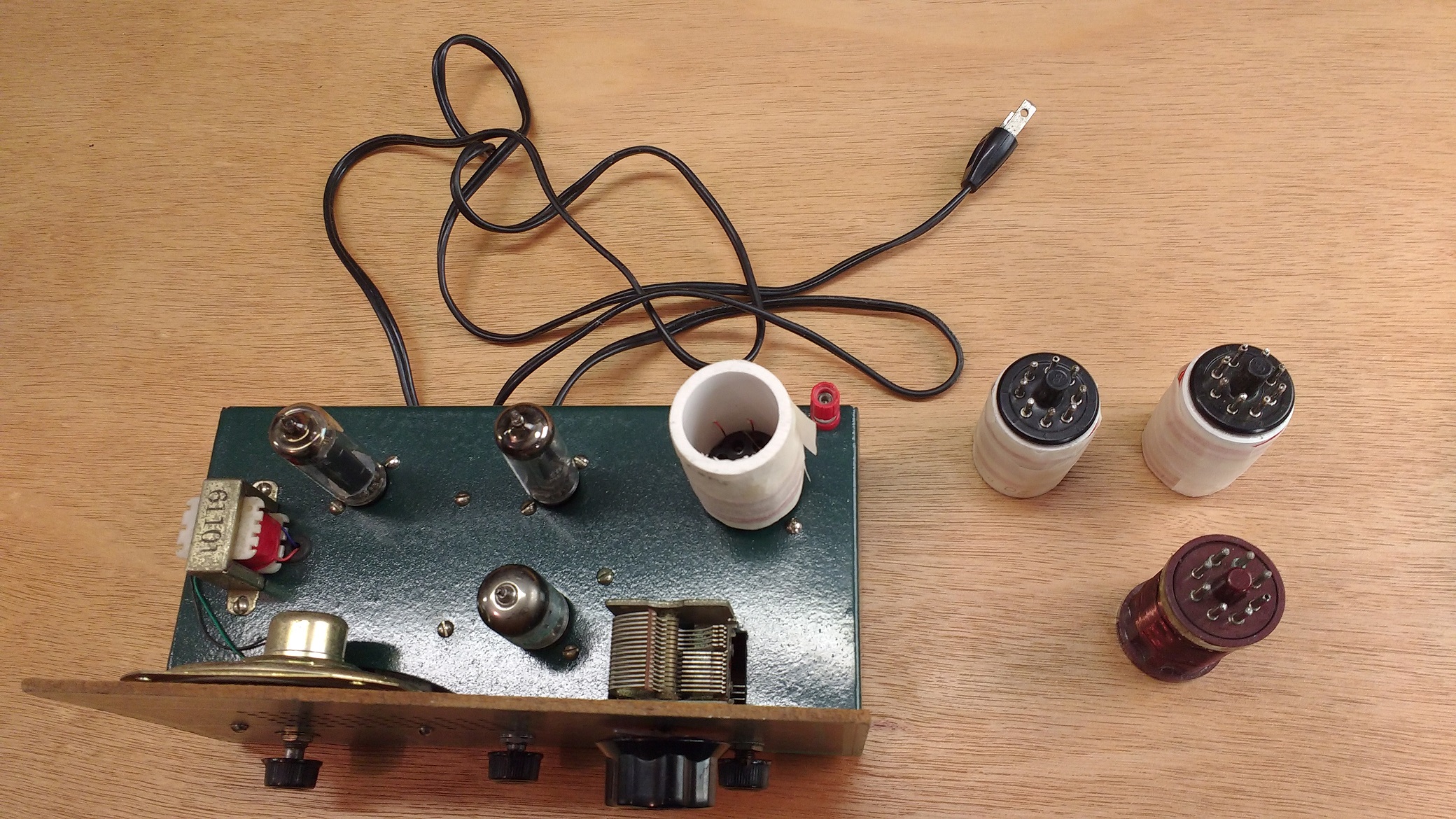
top view of the rebuilt chassis
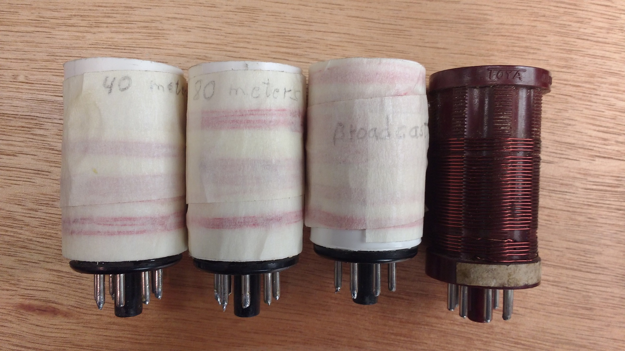
Only 1 original plug-in coil came with the radio – 3 additional coils were built using octal socket bases which are readily available and adding 1 inch plastic pipe lengths after some minor filing of tabs on the octal sockets using some epoxy glue – #24 enamel wire was used to wind the new coils – the 80 and 40 meter band coils were cut to place the amateur radio bands at the bottom of the range of the tuning capacitor which results in the widest bandspread to cover each band