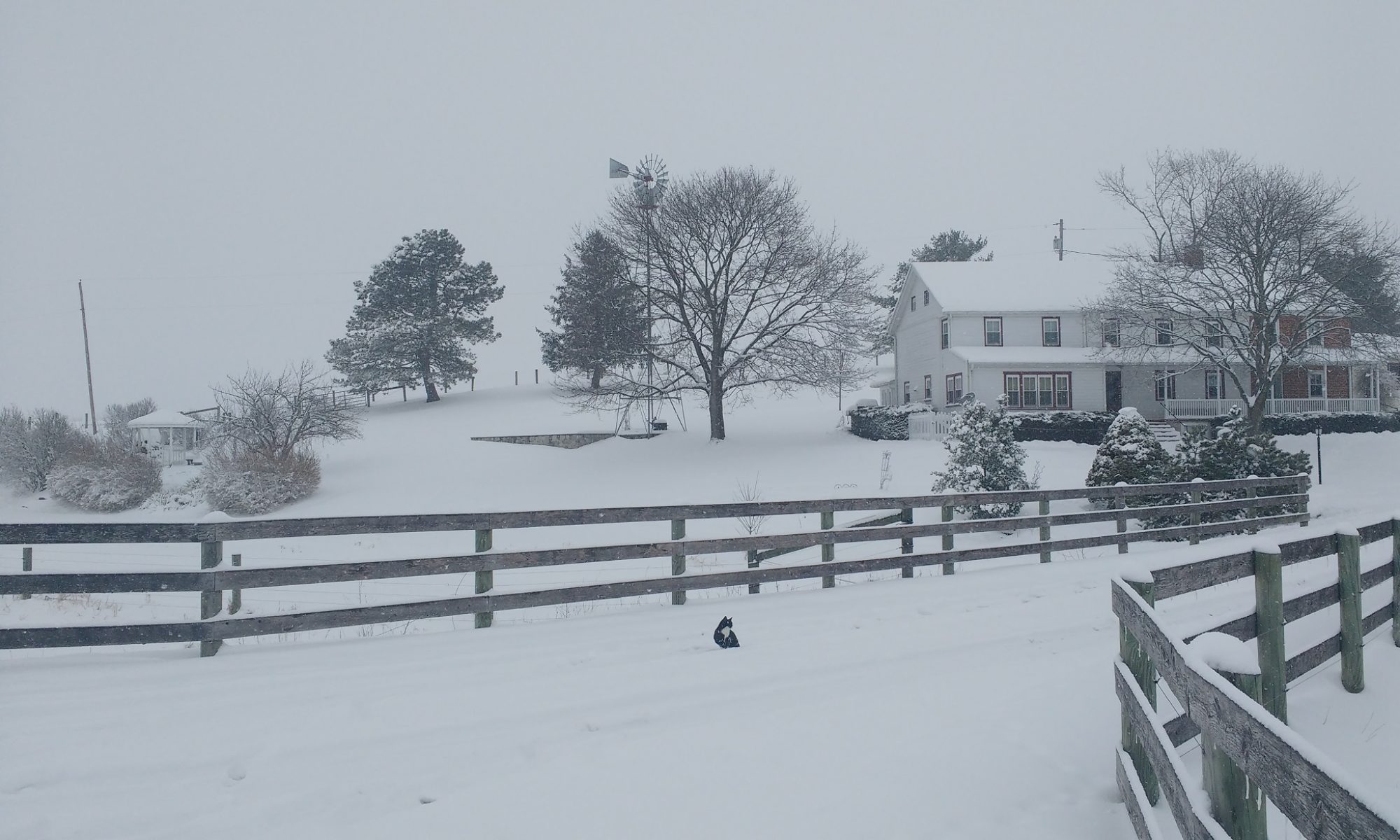
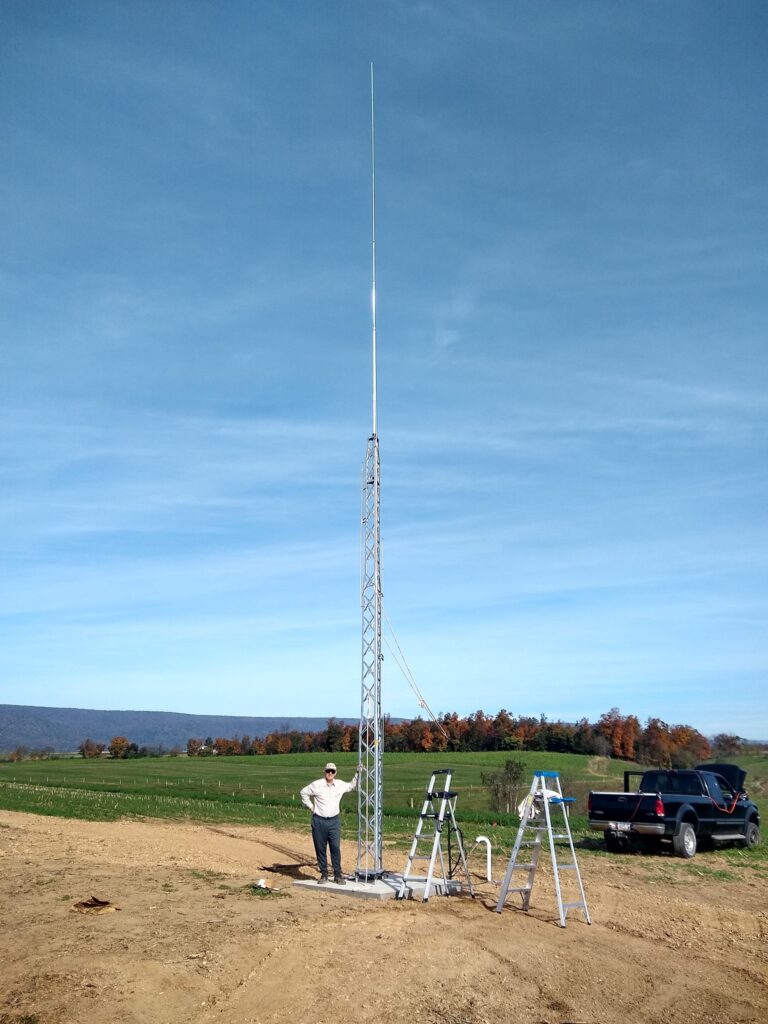
This popular antenna covers 80, 40, 20, 15 and 10 meters, providing low-angle radiation which is helpful for DX contacts. It has been available for many years. It does require a good ground radial system. My Hy Tower is located in a clear area in a field and about 200 feet from my radio shack. It is on a ridge and the land falls away in all directions except to the west, so that should be helpful for low angle radiation in all directions except to the west. The coax connection to the radio shack uses a 2 inch conduit buried about 2 feet in the ground which allows farming the fields to continue in that area.
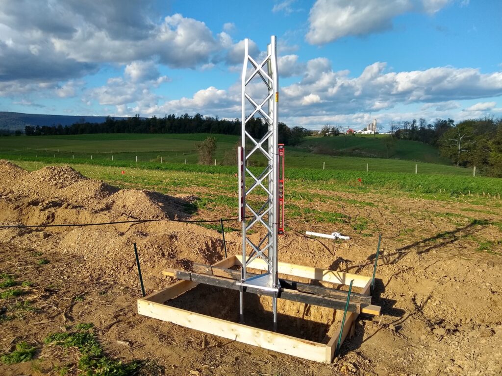
The Hy Tower base was prepared for the concrete pour by suspending the base and first 10 feet of the tower in the hole on a wooden form. Two levels were attached to the tower to allow monitoring of the vertical positioning of the tower base during the concrete pour.
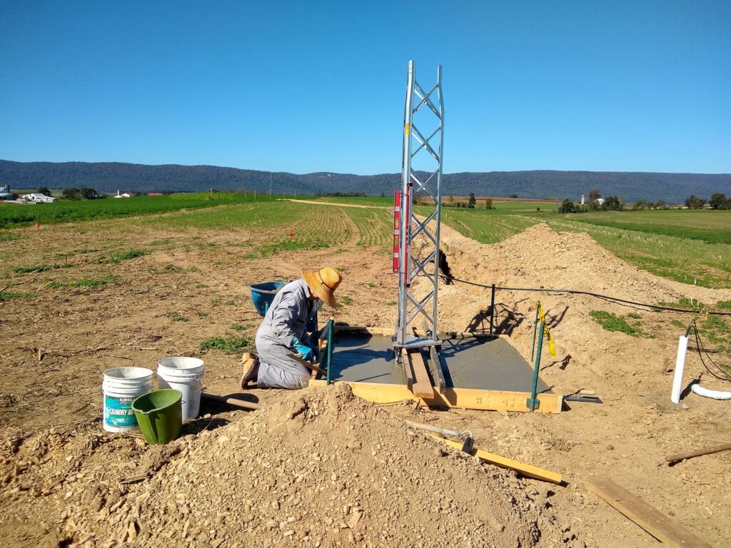
Joe Lockbaum (WA3PTV) finished the concrete after the main pour of 2.5 cubic yards by a commercial concrete company. The conduit for the coax cables can be seen emerging from the ground to the right of the tower.
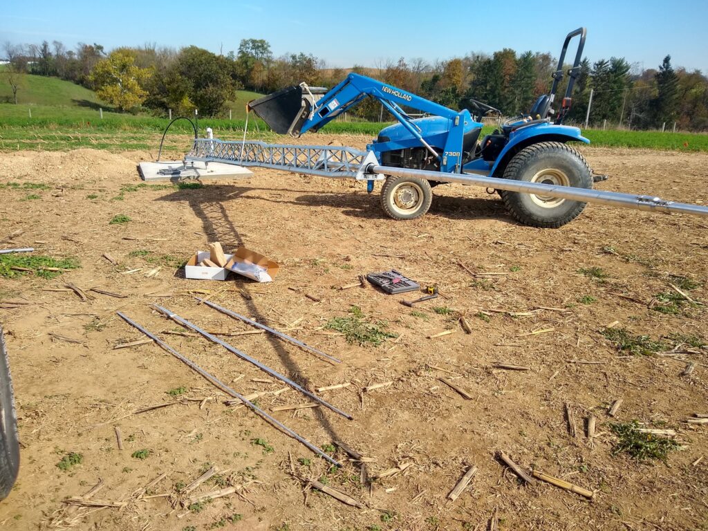
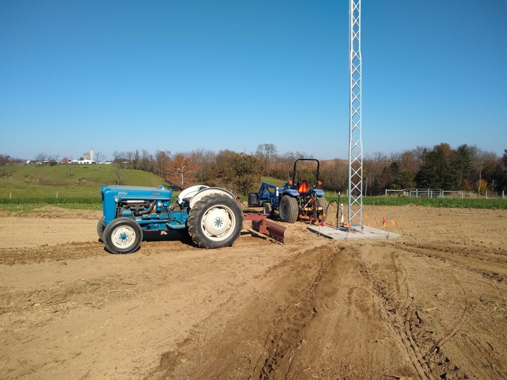
The New Holland front end loader farm tractor made it easy to lift the tower for installing the 3 stubs for 10, 15 and 40 meters.
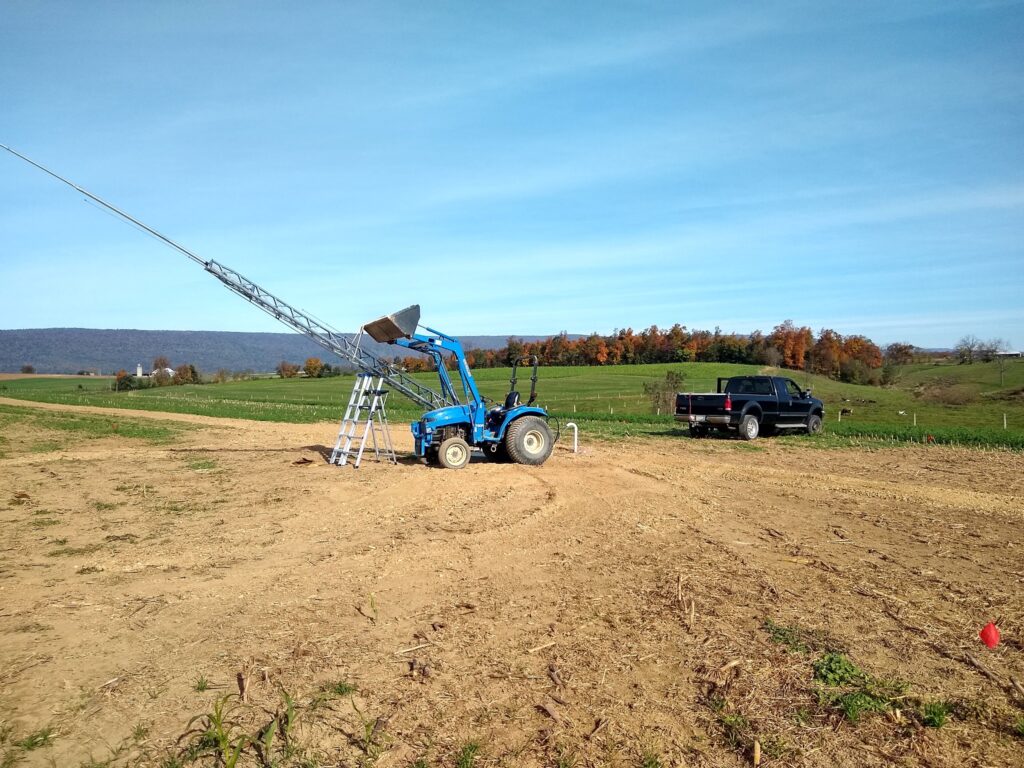
Here the front end loader with some precision operation lifted the tower to start the raising process. After an initial lift, the tower was lowered slightly onto two 6-feet step ladders, and the front end loader was moved for a 2nd and 3rd lift. Then a winch mounted into the receiver of the farm truck with a heavy rope attached to the tower at about 16-feet in height pulled the tower into a vertical position.
The 3rd and final lift by the front end loader
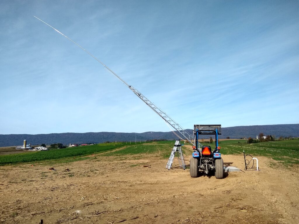
The start of the lift by the winch on the truck.
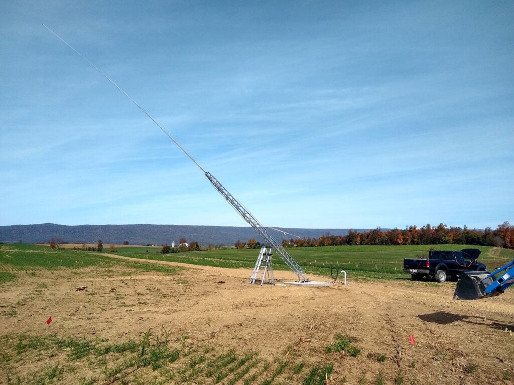
The tower here is almost into position. Soon after this point, my XYL stabilized the tower using a rope attached at about 8 feet up the tower and opposite the truck to prevent the tower from rotating too far towards the truck. It is important to move slowly and carefully to avoid losing control, and at this point only a few pounds of force is adequate to move the tower since almost all force in now down the tower into the base. My job at this point was to gently pull the tower into final position with one hand while positioned at the tower base and using the other hand to insert a bolt into the 3rd and free leg of the tower to attach it to the base.
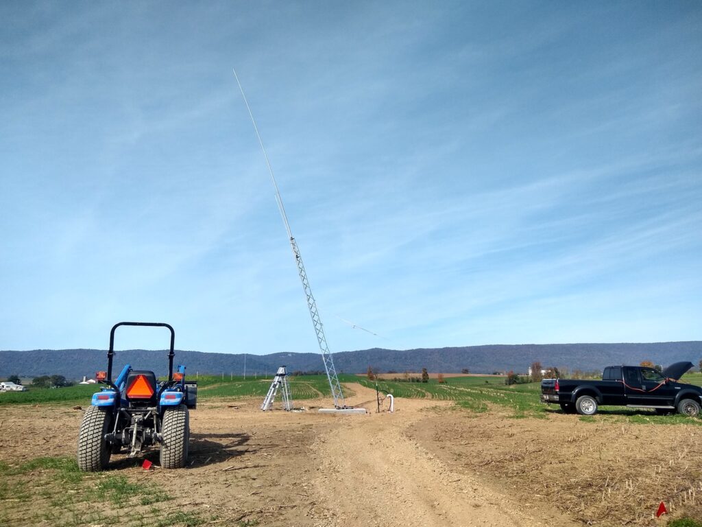
This picture shows the tower fully vertical and stabilized with all 3 legs attached to the base. The rope and cable for the final lift by the truck winch are still attached. They were easily removed using a short ladder.
The front end loader and truck winch did all of the heavy work for us. Having the farm equipment is definitely a plus for ham radio antenna work. Keeping safety clearly in mind is important. Using ropes, cables and equipment that are overrated for the job is one key. Another key is staying well clear of any position in danger if control of the tower were to be lost and it would suddenly drop. And good experience and knowledge using the equipment are required.
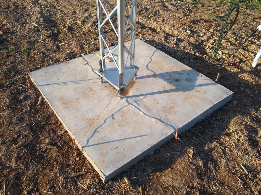
Six ground rods were initially driven into the ground distributed next to the tower base and 2 ground rods were attached to each tower leg base near the concrete. Heavy #8 solid copper wire was used. A few feet into the ground, heavy slate was encountered in this field and driving a ground rod became very difficult to impossible, so 4-feet ground rods were used. Driving the final foot was quite difficult for each ground rod. Thirty-two 45-feet radials were added to the ground system primarily for antenna performance, but they also enhance the protection for lightning.
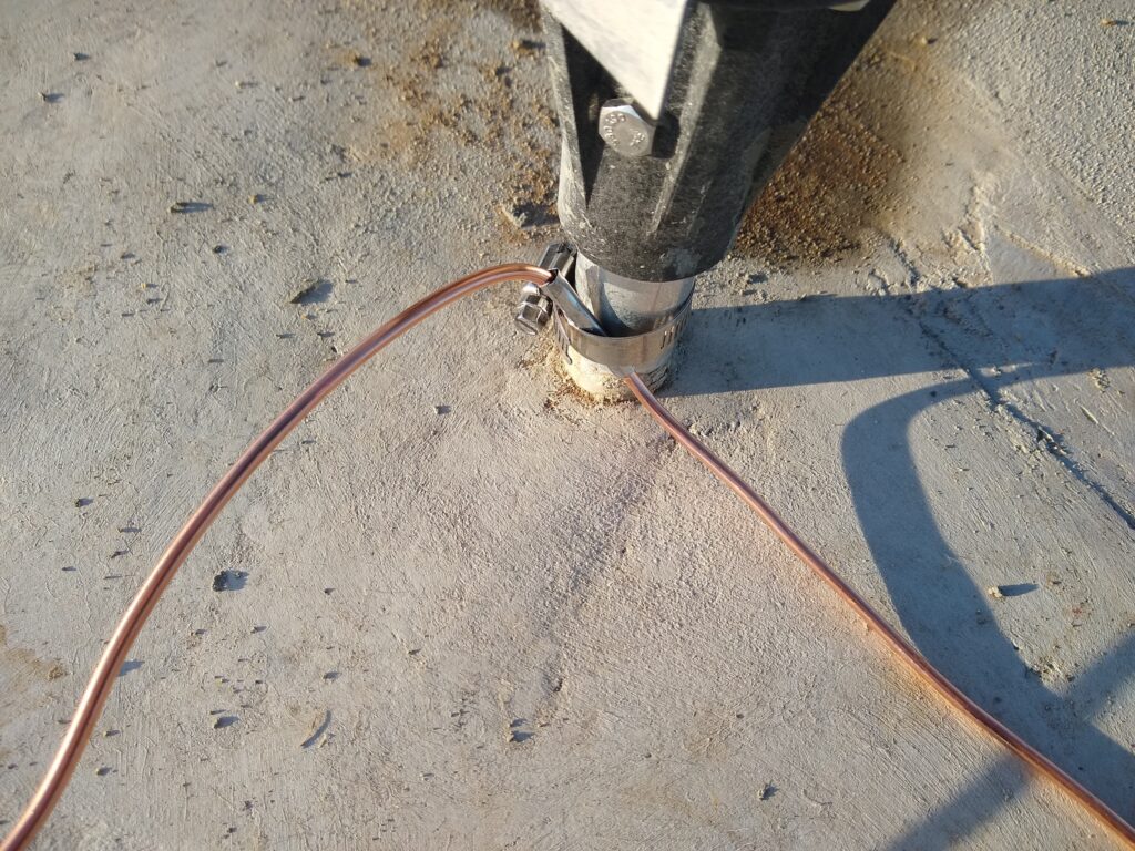
At each tower leg, a stainless steel pipe clamp was used to secure the copper ground wire. Also, a small thin sheet of stainless steel was wrapped around the copper wire at the tower base to prevent copper from touching the galvanized tower leg to minimize corrosion over time.
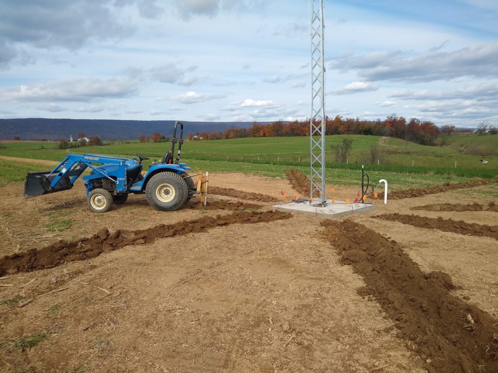
Plowing trenches for radial wires to about 6 inches depth with a potato plow. Placing the radials in the trenches was the harder part of this part of the antennas construction which involved removing large soil clumps from the trenches and securing the wire to the bottom the trench every few feet with a bit of soil prior to closing with the tractor and blade. But the tractors did almost all of the work overall. Eight trenches were dug at one time spaced at 45 degrees to avoid overlapping the trench soil near the tower, and then after closing the trenches, the next set of 8 trenches were dug. Small flags were placed at the tower base and at the outer perimeter to mark the trenches clearly for plowing.
This photo shows the process of closing the trenches with a scrapper blade. All tractor work was done pulling away from the tower to dig trenches and to close the trenches. Then the Ford tractor was driven along each trench to compact the soil. Later the blade was used to pull soil inward from the perimeter and then finally around the tower in a circular fashion to finish leveling the soil.
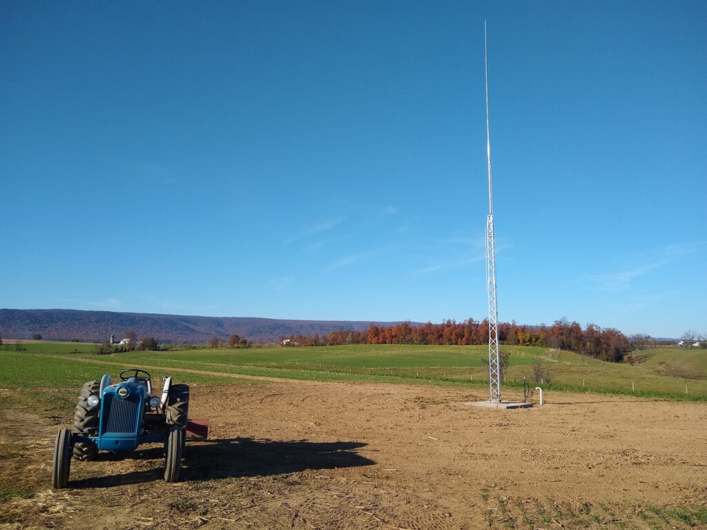
The tower and radial field after leveling the soil was complete with the Ford tractor and blade..
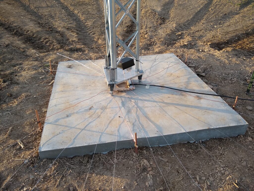
The tower base with 32 radials added each of length 45 feet. A DX Engineering radial plate is visible below the tower base plate. Above the tower base plate is an RCS-4 4-to-1 remote antenna switch modified to switch the Hy Tower across 3 segments of the 80 meters band with inductive loading. The manual for the Hy Tower recommends adding an inductor to load the antenna to use it on the CW band, but then the phone band has high VSWR. Here the RCS-4 antenna switch with some minor modifications of adding 2 inductors is used to allow remote switching of the inductive loading for 80 meters from the radio shack.
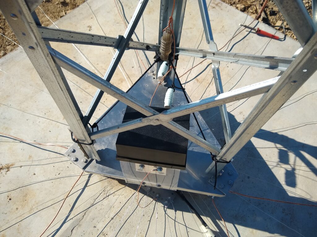
The coax from the radio shack connects to a SO-239 UHF female connector on the DX Engineering ground plate. The center conductor from SO-239 connects to the bottom side of the Hy Tower base plate (which is hot and insulated from ground) near its center directly above the ground plate, and a copper wire connects from the top side of the base plate to the center pin of the input connector on the RCS-4 antenna switch. The RCS-4 antenna switch is mounted on a piece of plexiglass to isolate the ground of the switch from the “hot” antenna base plate. A copper wire connects the ground of the RCS-4 down to the DX Engineering ground plate sitting below the tower base plate. This arrangement couples the control signal into the RCS-4 and then passes the radio signal through the RCS-4 to the vertical antenna wire inside the tower sections which connects to the vertical antenna tubing above the tower sections. Also the signal is directly connected to the tower sections which total 24 feet in height and provide base loading for 80 meters operations and stubs for 10 and 15 meters operations. The 24 feet of tower is insulated at the top from the aluminum tubing sections which extend above the tower to about 54 feet height and the vertical wire which is inside the tower sections..
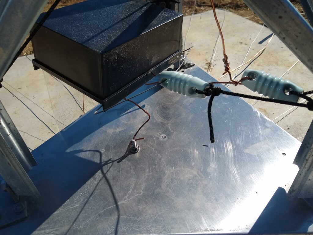
The signal from the tower base is connected to the common input on the RCS-4, and output #3 connects to the vertical 80 meters copper antenna wire (pulled to the side by an insulator). The second insulator connected to a short rope is for mechanical support. Only wires connect to the center conductor of the coaxial connections on the RCS-4 (for the input and for output #3 – the other outputs are not connected externally to the RCS-4), and the RCS-4 switches inductors into the base of the Hy Tower antenna on the 80 meters antenna wire.
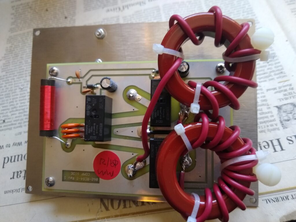
T200-2 toroid cores with 8 turns connecting ports 2 to 3 and with 11 turns connecting ports 1 to 3 are mounted on the RCS-4 PCB shown here with the outdoor cover removed. These toroids and the RCS-4 can support full legal power on 80 meters. So when port #3 is selected on the antenna switch, no loading is added since the inductors are bypassed. When port #2 is selected, the 8 turn inductor is in series with the vertical wire and when port #1 is selected, the 11 turn inductor is in series with the vertical wire.
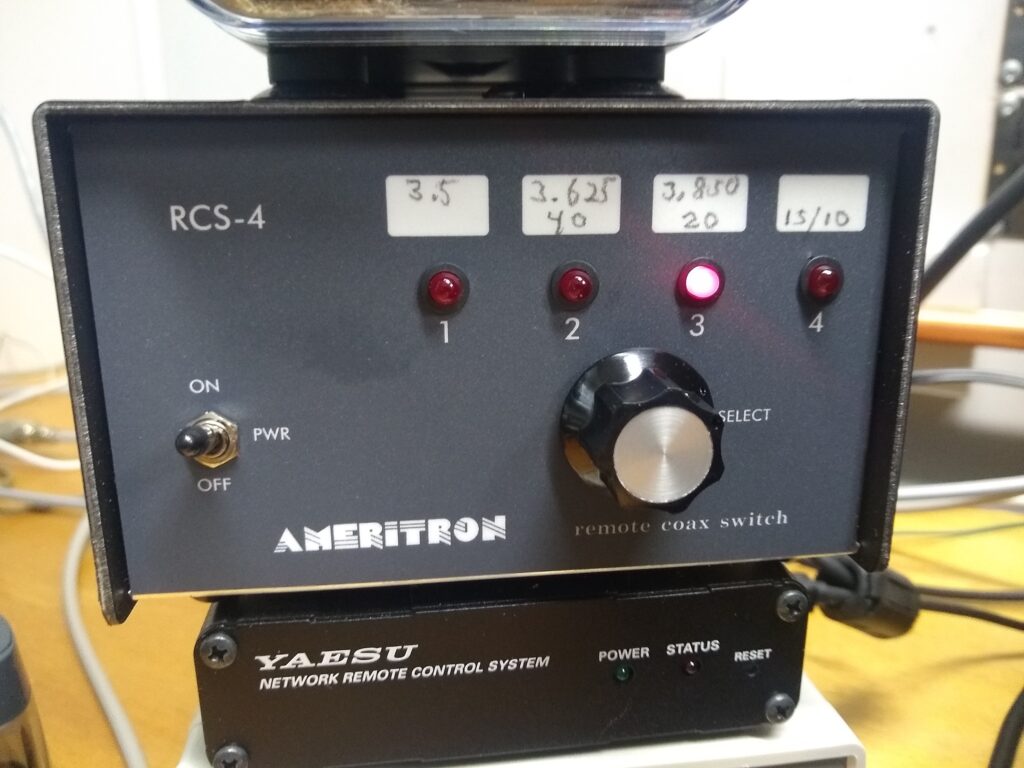
The RCS-4 control box in the radio shack showing the switch positions for the start of each band segment. The CW band is covered by the first switch position, and the phone band is covered by switch positions 2 and 3. Switch position 4 disconnects the 80 meters vertical copper wire, and this provides the best VSWR performance for 15 and 10 meters. This disconnects the center wire and top section of aluminum tubing of the Hy Tower during 15 and 10 meters operations and only the tower sections and 10 and 15 meter stubs are active.
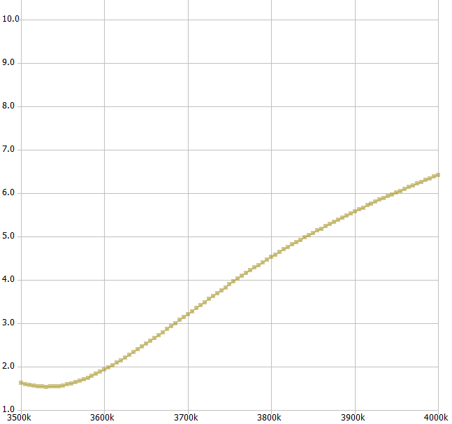
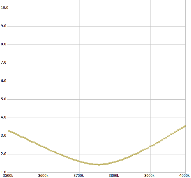
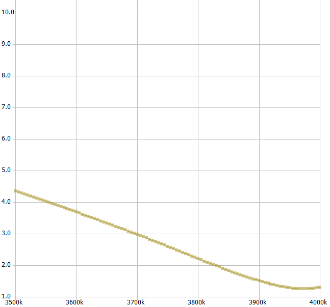
VSWR plots using a nanoVNA for 80 meters for RCS-4 switch settings 1, 2 and 3. Most of the CW band is covered at close to 1.6 VSWR in switch position 1, and the entire phone band is covered at less than 2:1 by selecting switch position either 2 or 3, except for near 3.625 MHz the VSWR rises to about 2.25.