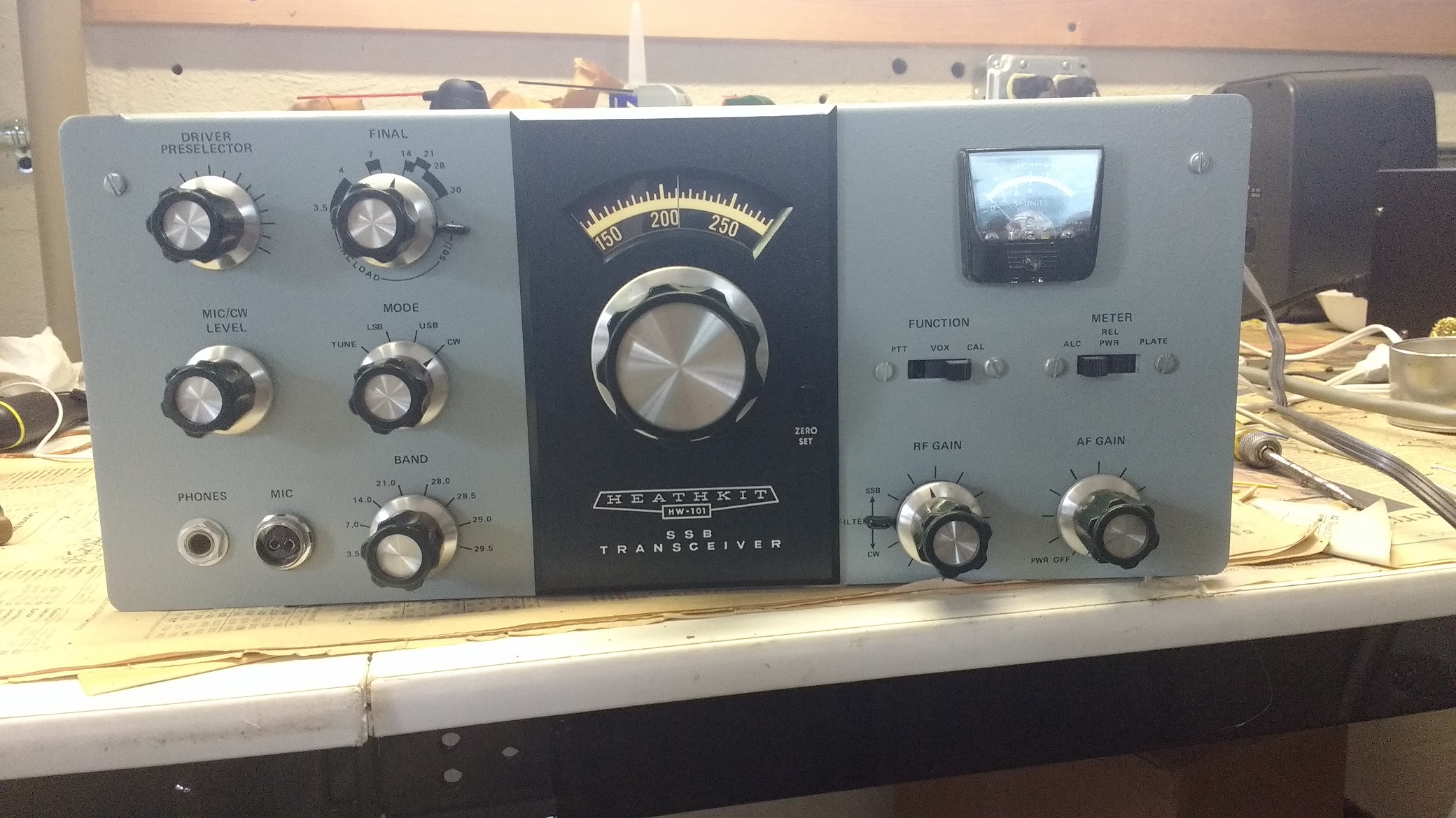
This Heathkit HW-101 was purchased in 1993 by KA2C and was unused for many years except for a few occasions. I decided to renovate it in 2018. There were a handful of problems.
1. The unit was dead on the 29.5 MHz 10 meter band segment. Reheating key solder joints on the crystal board and the heterodyne coil board did not solve the problem. Swapping in a new 29.5 MHz band heterodyne crystal from a parts rig did solve the problem
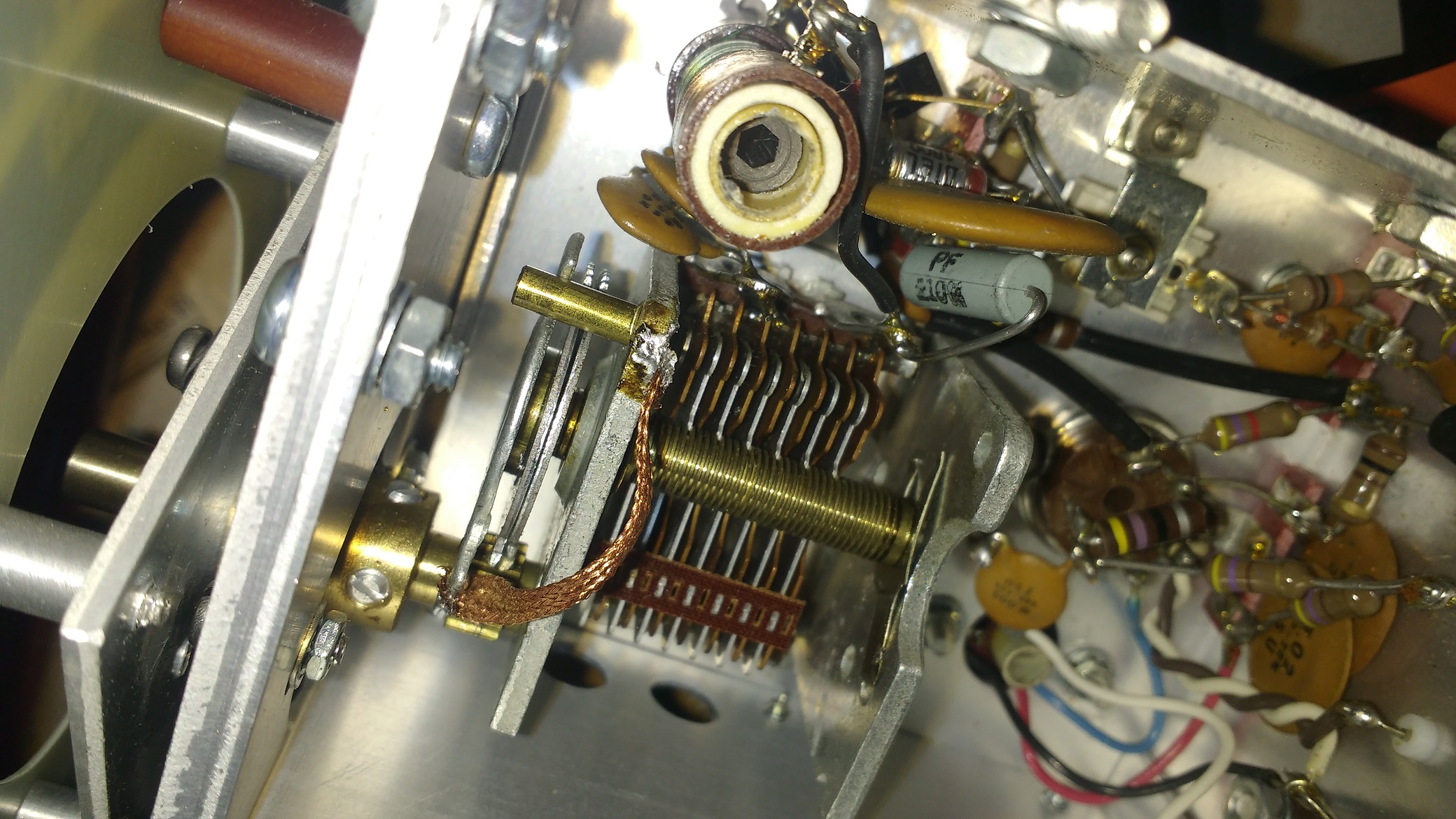
2. Transmit instability was observed on most bands. Further investigation showed that the driver board was oscillating. This oscillation was observed on an oscilloscope with the drive level turned completely down. This was improved by tightening the screws holding the boards to the chassis to make sure the ground connections were good, but this did not completely solve the problem. Visual inspection eventually found that the shield board between the pre-selector coil boards was loose on one side. There was considerable play between the board and the ground rails on either side, so a piece of flexible copper braid was inserted on one side and the shield securely soldered into position. With that fix, stability was good. The picture shows the solder connections on the shield board to fix this problem.

3. The VFO exhibited warble during operation. Instead of smooth tuning as desired, the frequency would jitter during tuning making it hard to accurately tune in properly both CW and SSB stations. The manual explains how to remove the VFO from the unit. This can be done fairly easily without removing the front panel, but be very careful to not damage the plastic tuning dial. First the 3 power wires are desoldered and the VFO output coax disconnected, and then the main front panel tuning knob is removed and the front Jackson reduction drive just behind the tuning knob is removed. A panel lamp mounted on the VFO chassis must also be disconnected.

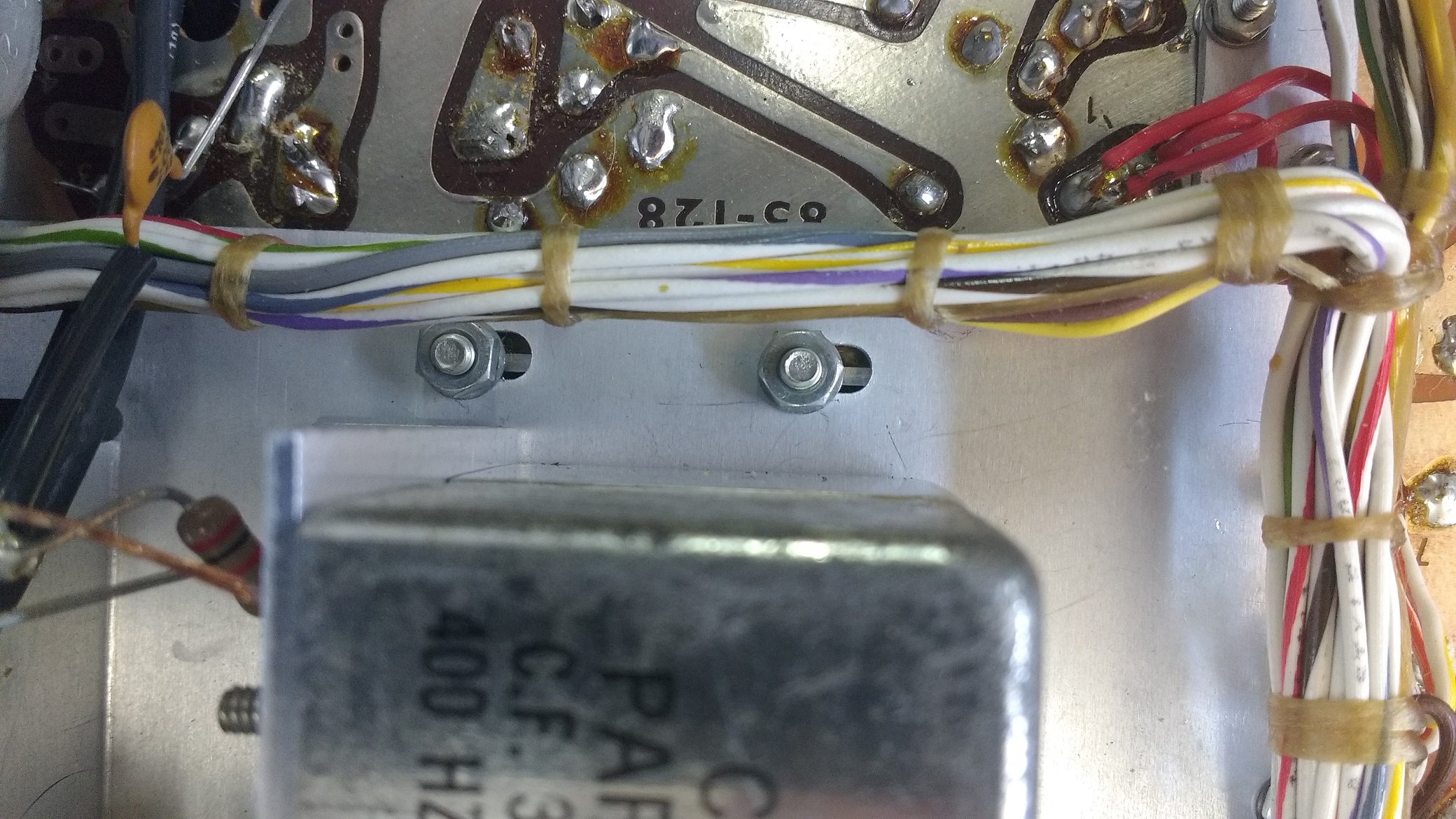
One of the hardest steps is to remove the 4 nuts holding the VFO into position. The main wiring harness obscures 2 of the nuts and removing several tie wraps allowed enough movement of the wiring harness to access those nuts. The nuts are also located very close to the crystal filters making access tricky. I used a small and medium sized needle nose pliers to loosen the nuts and remove them along with the lock washers. Three nuts were removed with the unit on its back, including the hardest to reach nuts, and a final easy access nut was removed with the unit on its side, so that the vfo did not fall out. This procedure was performed in reverse to reinstall the VFO. The nuts are gently moved into position on the bolts and then started onto the threads by gently turning the nut from the side with the needle nose pliers. A little practice on this may be needed to make this work.
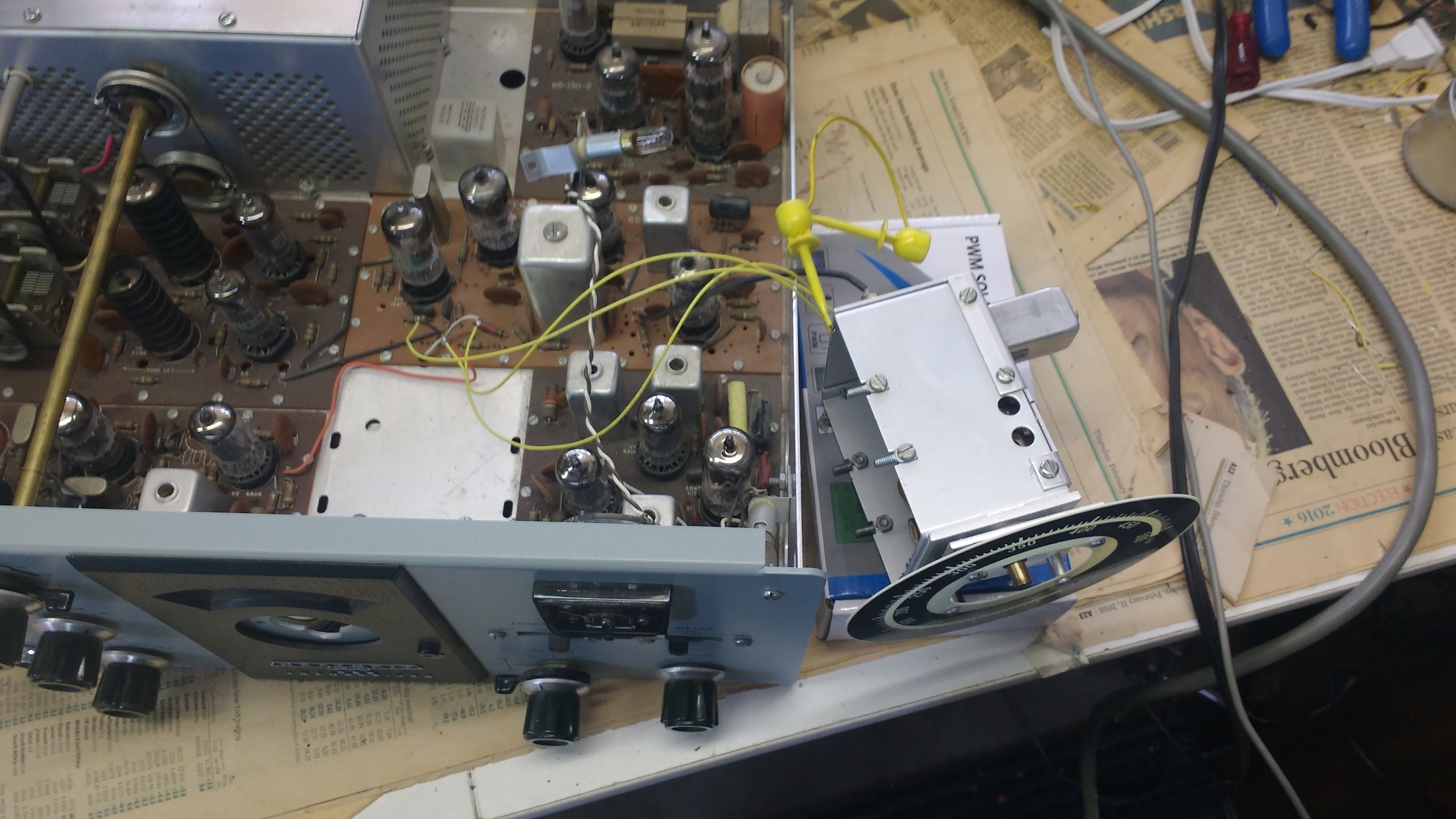
Once the VFO is out of the chassis, it can be reconnected with 3 extension wires to the power supplies and the VFO output coax reconnected, so that the HW-101 can be turned back ON and the VFO can operate on the bench.
Fixing the VFO involved several steps. A compressed air can was used to blow dust out of the tuning capacitor plates and out of the capacitor bearings as well as the entire VFO chassis. Then deoxit was used to clean the capacitor bearings being careful not to contaminate the electrical components. The bearings need to be re-lubricated with either a light sewing machine or similar oil or a conductive oil such as those with silver content. The final step involved making 2 ground connections. The first connection was a flexible copper braid connecting the rotating tuning collar directly to the capacitors grounded body. The connections of the copper braid and the length of the copper braid need to be carefully selected to avoid any binding or rubbing as the VFO is tuned from one end to the other. That alone did not solve the problem. The final step was a fixed short ground connection from the front side of the chassis to the capacitor’s body. Prior to adding the fixed wire, a screw driver shorting the VFO chassis to the capacitor body could cause about 1 KHz in shift of the frequency which disappeared after the ground wire was added. With these fixes, the change in performance of the VFO was dramatic. The jitter/warble disappeared so completely that it was no longer discernible and the smoothness of the tuning allowed tweaking the setting in steps perhaps as small as 10 to 20 Hertz without jitter or sweeping across a CW signal with a very smooth continuous tuning.
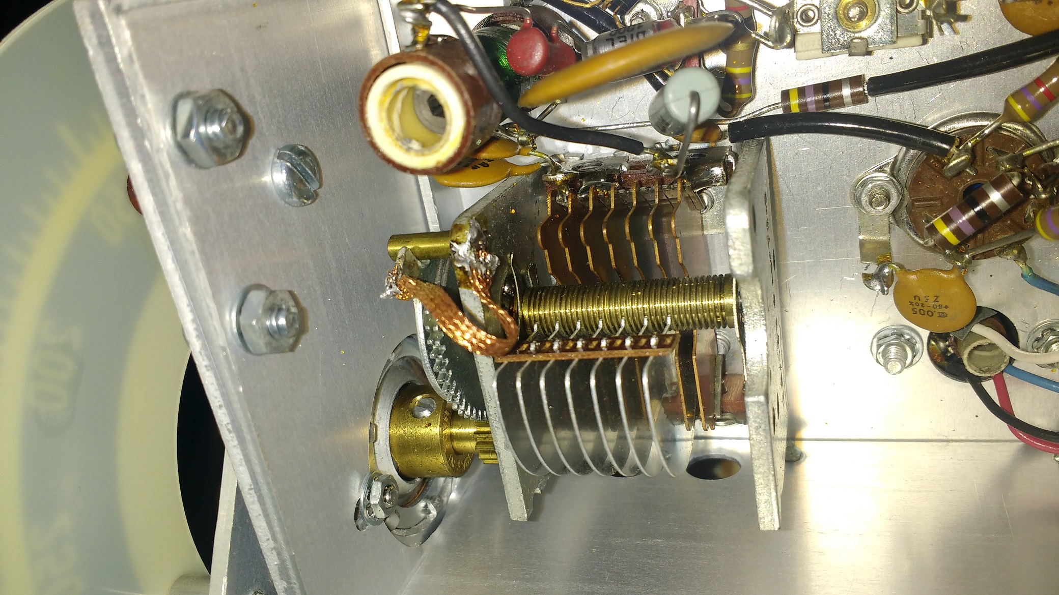
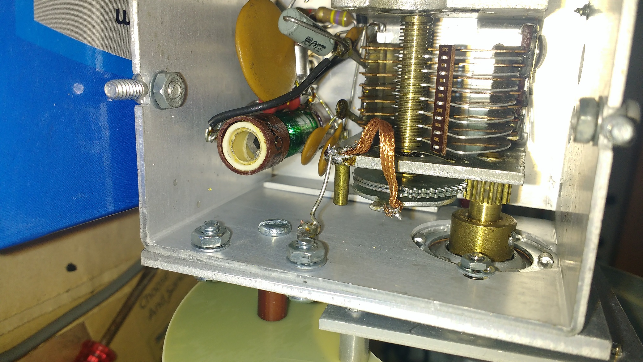
flexible copper braid connects the capacitor body to the rotating stop on the shaft, and a fixed wire connects the capacitor body to a solder lug on the VFO’s chassis
VFO warble before fixes
VFO after fixes – notice tweaking by small frequency shifts and smooth sweeps
4. A wire was added connecting the TX/RX relay control from the mic connector to a spare phono input to support foot pedal control of TX/RX.
5. The 1st IF V3 6AU6 tube had an intermittent noise problem and it was replaced. Since it happened only at times for short periods of time, tracing this problem was somewhat difficult, but the best technique involved shorting the RF signal with a capacitor to ground at different stages of the RX combined with stimulating the problem with ON/OFF cycles to find what locations silenced the noise and thereby localizing the problem.
6. The USB/CW/LSB carrier injection crystals were measured at 3.39628/3.39544/3.39364 MHz. The factory targets are 3.39640/3.39540/3.39360 MHz. The CW crystal was only 40 Hz off the factory target, and the USB crystal was 120 Hz off, and the LSB crystal was off by 40 Hz. The CW filter appeared to peak at about 1000 Hz for reception, but I prefer CW at 700 to 800 Hz, and I also prefer good bass for SSB. For compensation, a 24 pF capacitor was added parallel with the USB crystal to lower the frequency 240 Hz, resulting in USB/CW/LSB frequencies of 3.39608/3.39544/3.39364 MHz. With these adjustments, CW signals peak at 700 to 800 Hz for receive, and the USB crystal (used to receive CW) and the CW crystal (used to transmit CW) are offset by 640 Hz which means that the transmit signal will be zero beat with the received signal when the received signal is set to 640 Hz near the peak of 700 to 800 Hz. The received noise pitch sounds nearly same for USB and LSB indicating that the frequency offsets are nearly equal from the center of the SSB filter. With 2.440 KHz difference between the USB and LSB crystals versus 2.800 KHz in the factory targets, this indicates that the USB and LSB carrier injection crystals are about 180 Hz closer to the carrier than the factory targets which provides better bass for both RX and TX.