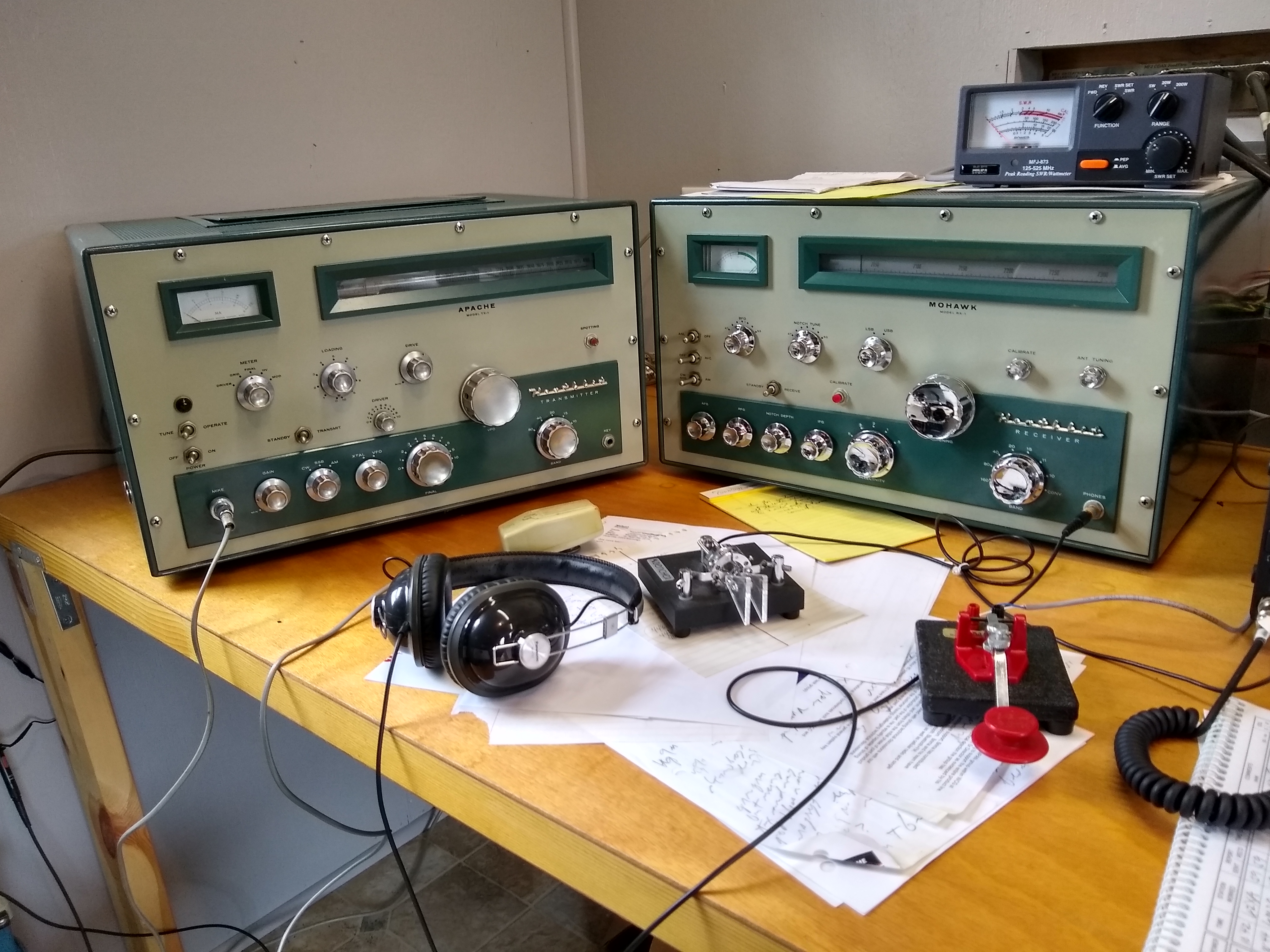
I acquired a paired Heathkit RX-1 Mohawk receiver and TX-1 Apache transmitter in the mid-90’s in very nice condition and kept them in storage for over 20 years. They appeared to have been assembled by a very careful ham and also were kept in excellent condition. The TX-1 is a good option for AM transmission with plate modulation. They are known as “boat anchors” due to their large size and weight with the TX-1 coming in at about 110 pounds.
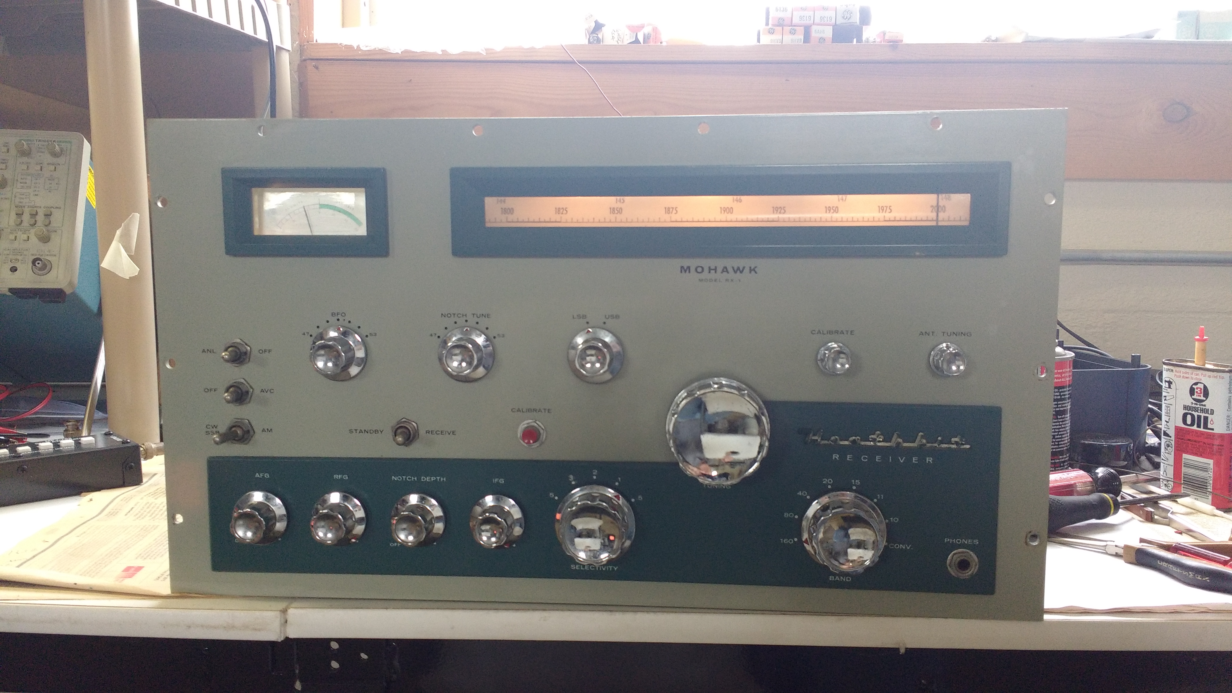
RX-1 Mohawk receiver
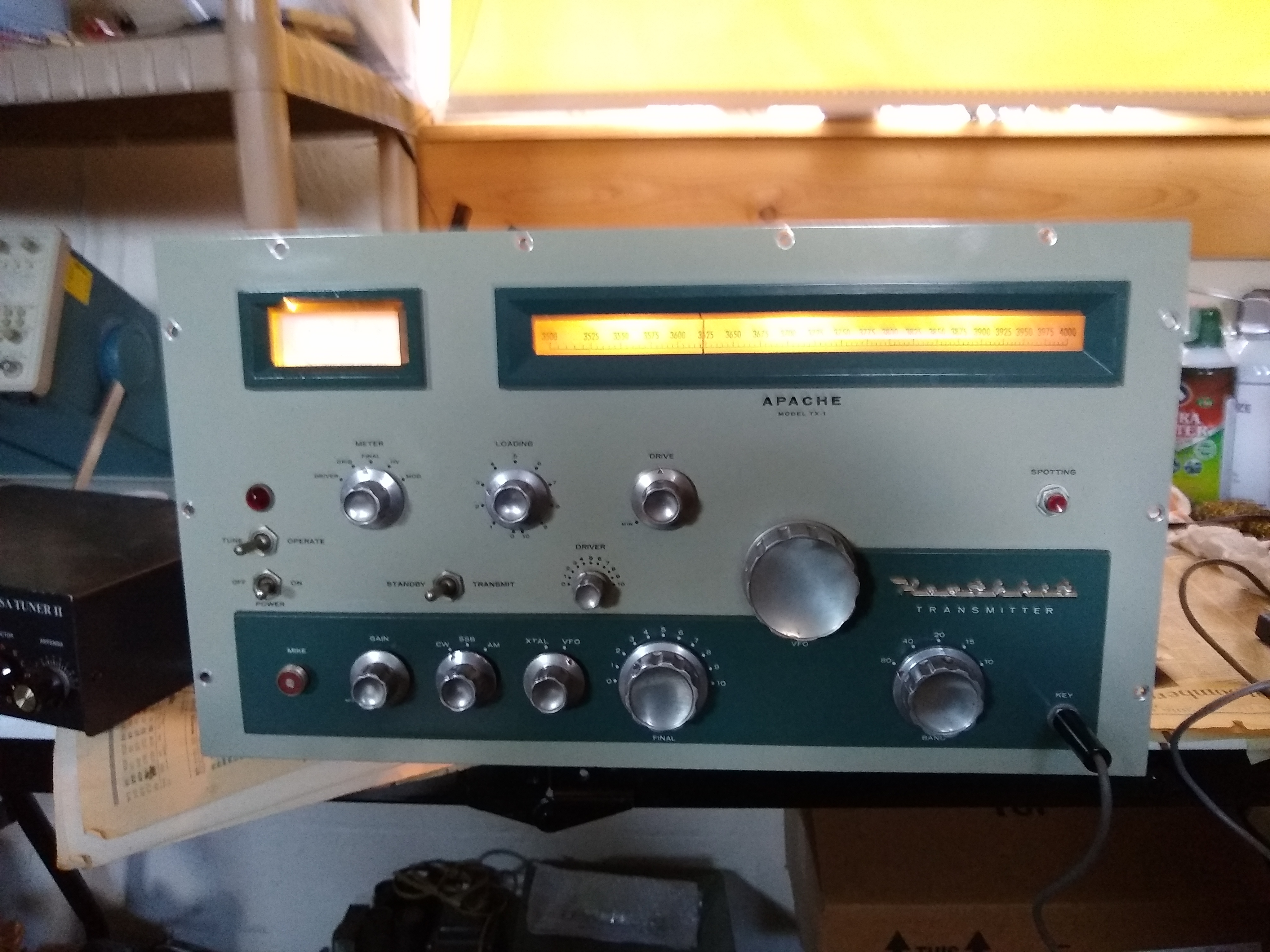
TX-1 Apache transmitter
In 2017 the RX-1 was brought up. The first step was a thorough cleaning of the chassis, front panel, knobs,…. with warm soapy water while avoiding excess water on the components. Then the switches were cleaned with contact cleaner and the tube pins were cleaned with a pencil eraser. After bringing up the power supply gently with a variac, the receiver came to life. I soon discovered that the 1st conversion oscillator which varies in frequency with one stage of a large 3 section capacitor to tune the receiver across each band had some issues. It was generally working OK, but it was a bit erratic with sudden small jumps in frequency as the dial was tuned instead of the desired smooth tuning. A few basic cleaning steps did not fix the problem. I finally determined that the sliding wiper contact on the large variable capacitor was probably the issue. After cleaning it with contact cleaner it was still not OK. In the end, I had to brush it gently at the points of contact with a very fine metal file. That will tend to remove any surface metals such as silver coatings, so I did this gently and for just a few swipes and then applied more contact cleaner. That finally restored smooth tuning!

The front section of the 3-section large variable capacitor tunes the variable oscillator and had dirty or corroded wiper contacts causing erratic tuning.
The RF and IF sections of the RX-1 were tuned according to the manual. After that the receiver showed expected sensitivity and selectivity. The RX-1 uses a 50 KHz final IF. This type of low IF was fairly common in the 1950’s and allowed narrow filtering for CW and a selection of wider filter options for SSB and AM using switched RLC tuned IF stages.
The TX-1 was brought up in 2018. After cleaning the chassis, front panel, knobs, switches and tube pins, I pulled the RF final tubes and the audio amplifier final tubes, and brought it up on a variac with a eye on the high voltage power supply and its filter capacitors in particular. The filter capacitors were OK initially, and after some time I brought them up to full voltage. Even at full voltage they were initially OK, but after 5 to 10 minutes they started to pop and breakdown with sudden short surges in current. So I decided to swap in new capacitors.

The TX-1 shown under the chassis with the old high voltage capacitors (the large black tubes near the top of the photo).
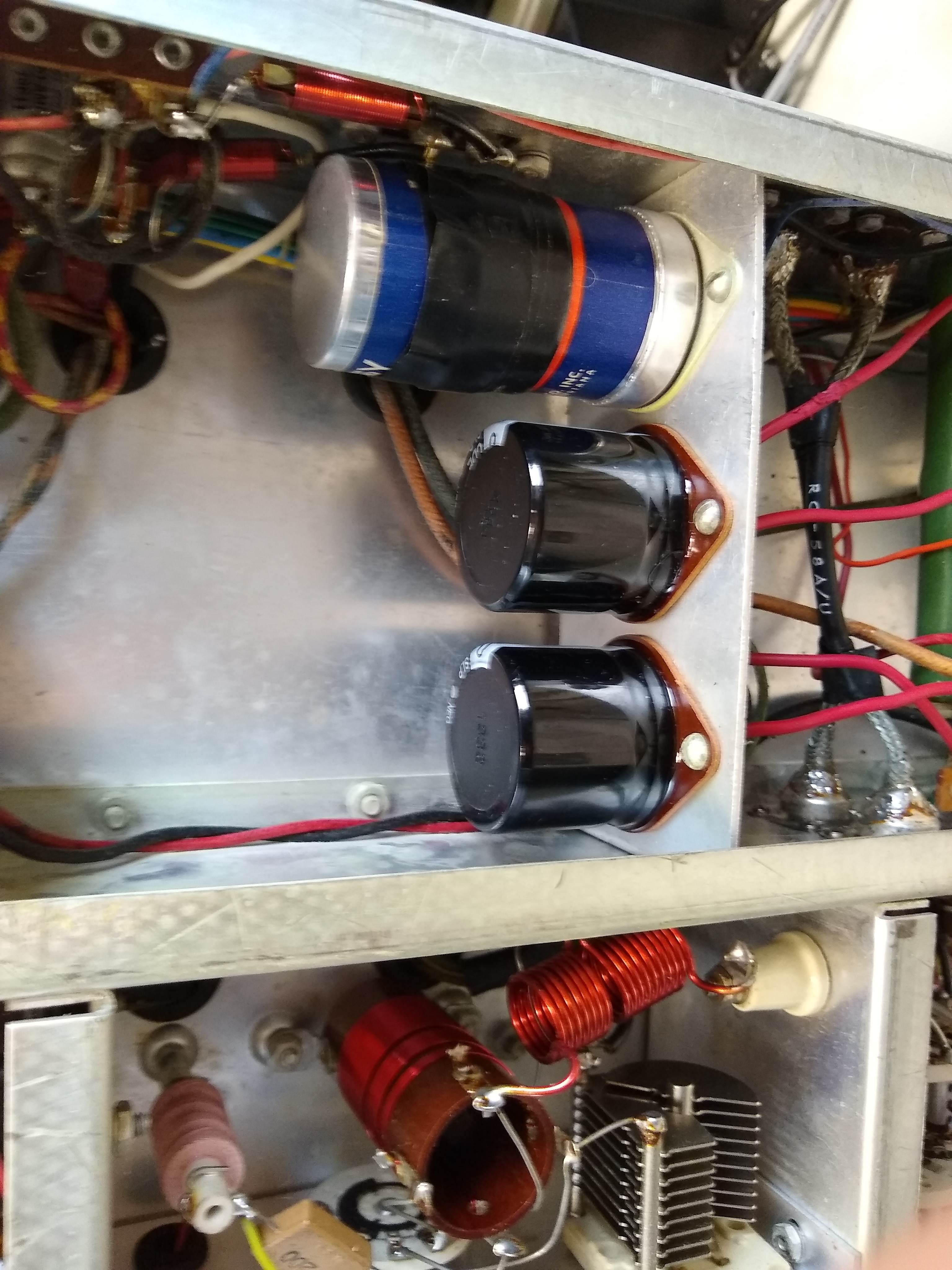
New filter capacitors were installed for the high voltage plate power supply. They are much shorter than the old capacitors. I removed the old capacitors from the brown phenolic bases and then attached the new capacitors with epoxy to the old bases and mounted these assemblies in the chassis and resoldered the connecting wires. With the new capacitors the high voltage power supply was fine.
I then tested all of the power supplies and found that everything else was fine. Using a receiver for testing, I found that the VFO and TX pre-amplifier stages worked OK. After insertion of the final RF amplifier tubes, the TX appeared to have instabilities, at least on the 40 meter band. The finals were 6146’s and probably original with the transmitter. I decided to swap in 6146A’s from a SB-101 parts rig, and that appeared to resolve the instability issues.
The tuning and control of a 1950’s boat anchor is much more complicated than modern rigs and is even a bit more complex than 1960’s and 70’s rigs. As was typical for the era, the TX-1 has separate switches for the plate power supply and the other power supplies (filament and low voltages). It also has tuning for the RF pre-amp stage. Finally, the loading capacitor for the final does not have any switching of value from 80 meters to 10 meters, so it needs to be set near maximum value for 80 meters and near minimum value to 10 meters. After some familiarization with the controls, and taking care not to overload/overdrive the transmitter, I was able to tune the transmitter up to over 100 watts of output power. The idle current of the 2x 6148A finals was running high in CW mode at nearly 100ma while it should be close to 0 ma. After some study of the manual, it became clear that both the final bias setting and the clamp tube setting would affect the idle current. It turned out that the key issue was adjusting the clamp tube setting, and it was a fairly sensitive setting.
Next I tested the audio amplifier, starting with the pre-amps and inserting an audio signal at the microphone input. That also was fine, so I reinstalled the audio final tubes and proceeded to test the full audio amplifier chain which was fine. Finally, I turned the rig to AM mode with a sine wave injected at the microphone jack.

Operation with modulation input of about 800 Hz and AM RF output of the TX-1
I then began detailed exercise of the TX-1 transmitter in CW and AM modes. It quickly became apparent that the VFO had some issues. It needed calibration, but the more serious issue was erratic tuning behavior similar to the RX-1 before it was fixed. For the TX-1, the VFO tuning capacitor is located inside the VFO box.
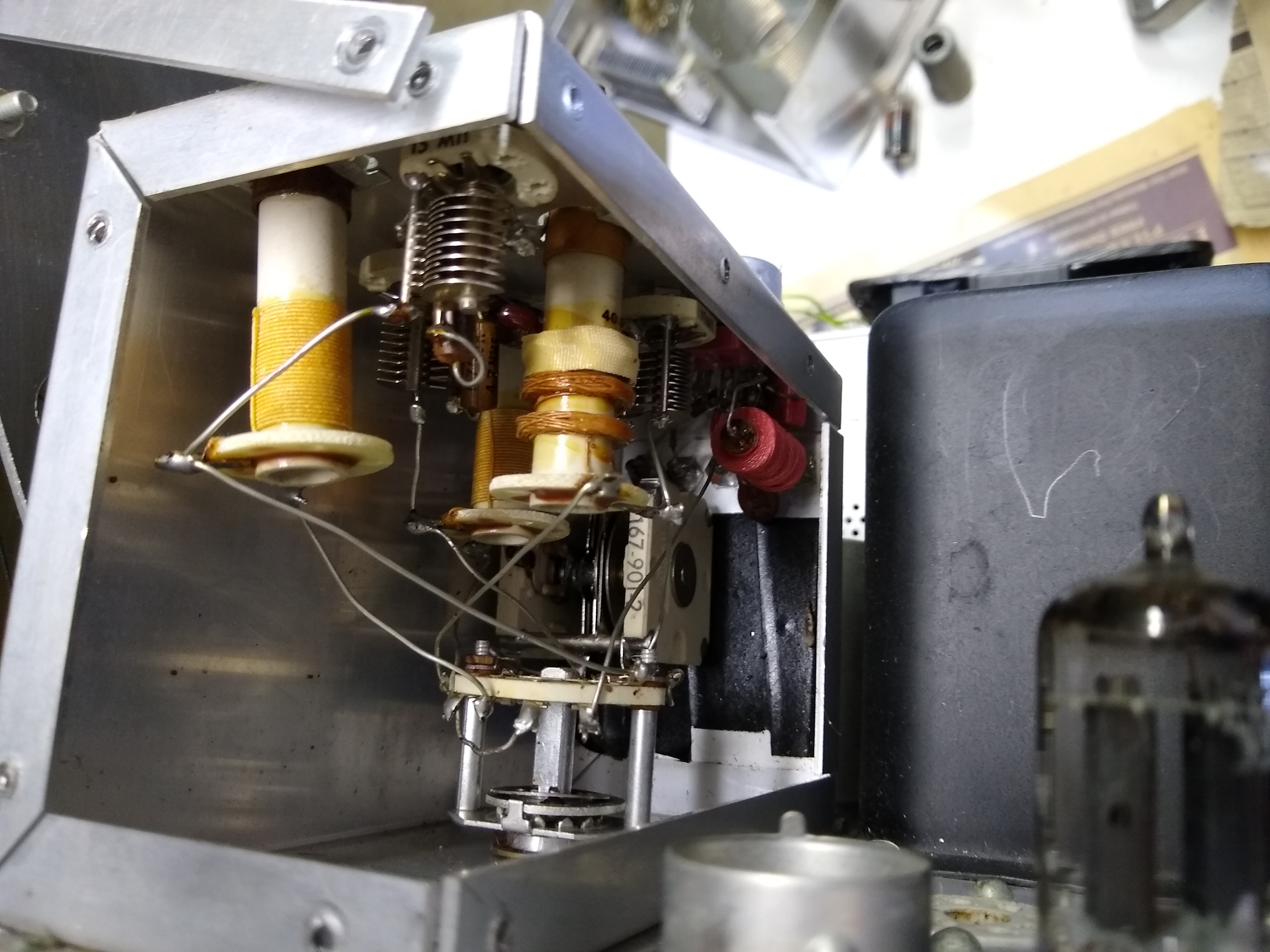
An L-shaped cover on the rear of the VFO was easily removed to examine the interior of the VFO. The variable tuning capacitor is in the back of the photo above. I applied some high performance electrical conductive grease with silver particle content to the wiper contacts on the tuning capacitor and rotated it a few times with the tuning dial, but there was no improvement in the problem. So I proceeded to remove the VFO from the main transmitter chassis. This required a bit more effort, but was not very difficult. Four screws under the main chassis held the VFO in place. In addition, a gear for the bandswitch in the VFO was located under the main chassis and needed to be removed, and the power supply wires needed to be desoldered.
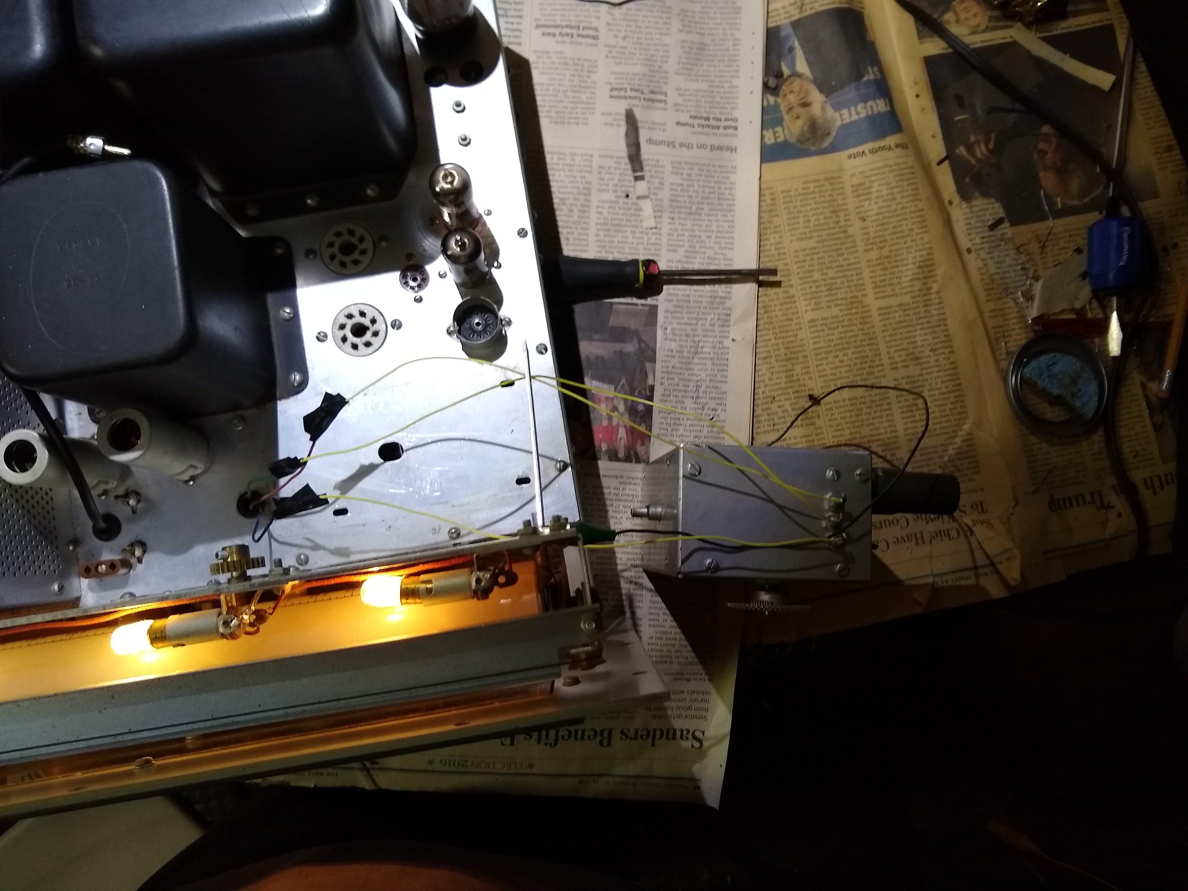
The VFO was placed beside the main chassis and extension wires were added to connect the ground, and filament and plate power supplies for the VFO. This allowed operation and testing of the VFO. The erratic tuning was not evident with this external operation which was puzzling. After returning the VFO to the main chassis, the erratic behavior returned! An anti-backlash gear is mounted on the shaft of the VFO tuning capacitor. It consists of 2 thin gears with 2 small springs that press the teeth of the adjoining gear from both sides by twisting the 2 thin gears to minimize any play in the gears. I found that pressing a screwdriver against the teeth of the 2 thin gears appeared to fix the erratic VFO tuning, and I realized that since the 2 thin gears can move with respect to each other slightly and that the springs can also move slightly that any corrosion of those components could result in small changes in electrical resistance and then affect the VFO tuning slightly. I then sprayed the small springs with contact cleaner and rotated them a number of times to rub off any corrosion. Finally I applied electrical grease. After returning the VFO to the main chassis, the problem was resolved.

A top view of the main chassis after completion of bring up. A new thin and quiet 120VAC fan was installed on top of the final RF amplifier cage . Since the RF amplifier runs with 100% duty cycle in AM mode, the tubes can easily overheat and cooling with a fan is needed.
The next step was to calibrate the VFO per the instructions in the manual using a receiver with a 100 KHz calibration crystal as a reference.
The TX-1 was designed to limit the low-frequency response severely. The 1st and 2nd stage pre-amplifiers have RC coupling in their outputs with 3 dB attenuation points at 600 Hz or 6 dB attenuation at 600 Hz overall. The high end is much more reasonable with a fairly slow roll off above 3000 Hz. I decided to improve the low-frequency response. 3.3 nF capacitors were added in parallel with the 510 pF coupling capacitors at the outputs of the 1st 2 stages in the audio amplifier chain. This improved the 6 dB attenuation point to about 150 Hz. It appears that some hams have made much more extensive modifications of the audio processing in the TX-1, in some cases largely replacing it. I’ve decided to leave the rest of the audio processing alone, at least for now, including the clipper (which was adjusted) and the following low pass filter above 3000 Hz. While this is a fairly primitive form of level control and audio compression, it should be OK if not overtaxed with excessive drive.