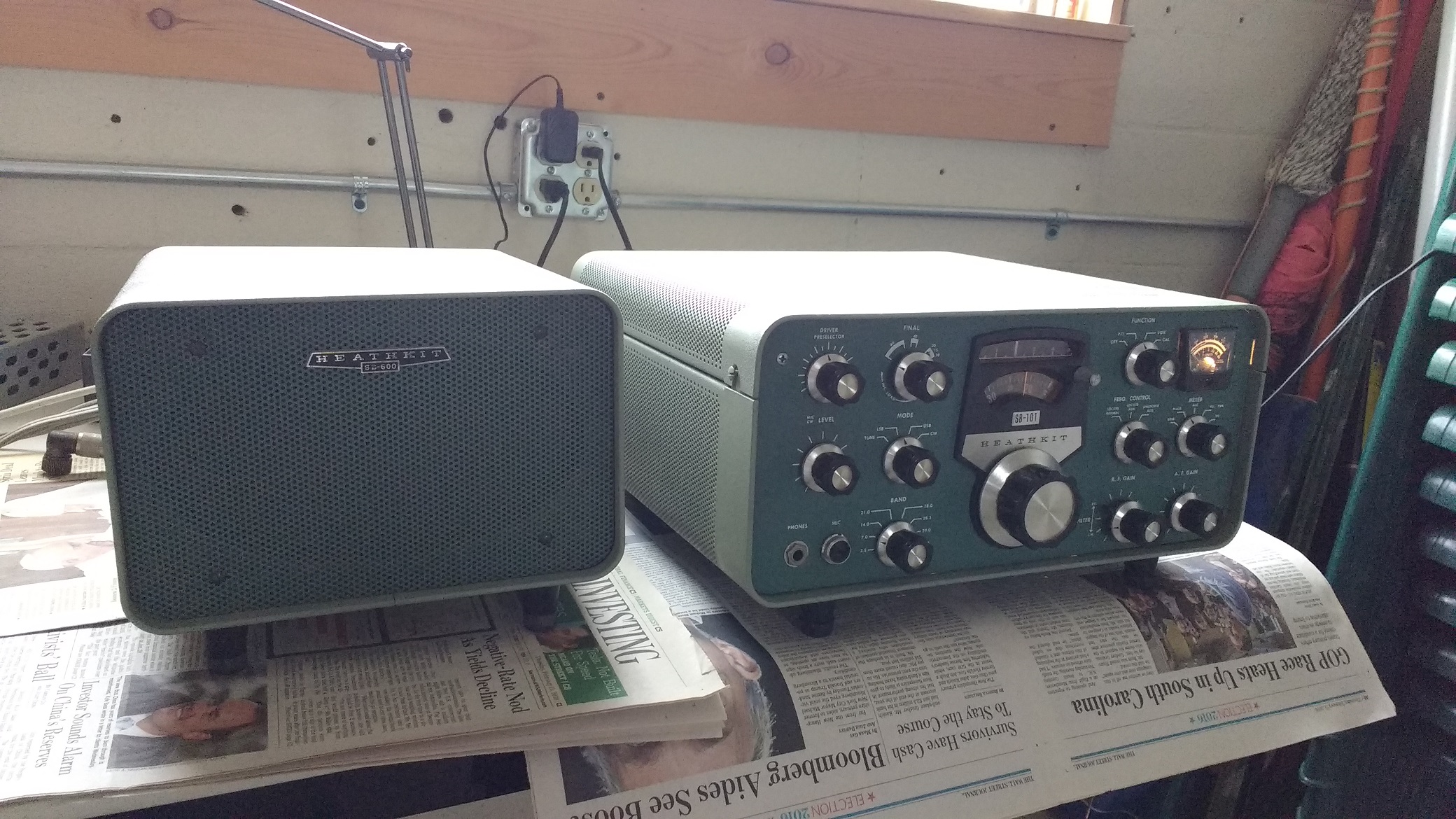
Heathkit SB-101 repair/mod notes
This unit was 1970/71 vintage and purchased by KA2C in 1973 (WA3PKU at the time) serving as the primary rig until 2012 – renovations performed in 2016 – 2018 – performance is now better than when new!
- The VFO had the well known “warble” problem in Heathkit rigs caused by hardened oil in the tuning capacitor bearings which act as a ground path for the moving plates. Following published notes by K9STH, this was fixed by opening the VFO and connecting a flexible braided copper strap from the rotating shaft to the chassis ground. See: www.k9sth.net/amateur-radio-k9sth under Heath Equipment.
- The physical spacing of the VFO was low (possibly due to slight metal deformation over many years) resulting in slippage of the tuning knob. This was corrected by placing a washer under each mounting screw for the VFO.
- The ON/OFF switch burned out. It was replaced from a parts rig
- After a long transmit, the receiver AVC would go high and quiet the rig making it hard to hear weak signals. This was a long time problem in this unit, and only diagnosed after some significant effort. This was caused by the screens of the RF driver and finals pulling the attached circuits positive when the tubes had warmed up well. After a long TX period, the TX finals and driver can be quite hot, and then the screen grids show considerable positive pull on the circuit. That circuit also was attached to the screen of the isolation amplifier (and is supposed to be blocked in RX) for the balanced modulator, and this circuit was pulled positive also, which unblocked the isolation amplifier and allowed carrier to leak into the receiver IF’s and hence trigger the AGC. Since this signal appeared at zero beat, it was not audible. The fix was to isolate the RF driver and RF final screens from the rest of the circuit with a diode, allowing their screens to be pulled high during transmit, but not allowing them to pull the rest of the circuit high during receive. A 1M resistor was added to drain the screens to ground also. And a 1.5 M resistor was added across an existing 1 M resistor in the bias circuit connected to the negative bias supply to further pull the isolation stage screen grid negative during receive. Later research on the Internet yielded information from 1978 from Heathkit with a fix for this in the HW-101 using a spare contact on the TX/RX relay to ground the final screen grids during RX. It also appears that later versions of the HW-101 included a diode in the circuit for the finals’ screen grids similar to the fix added here, however it did not include the driver’s screen grid. Apparently this problem existed for over 10 years in the SB-100 series and the HW-100 series before it was understood by the community and a fix provided. It must have frustrated many hams.
- The balanced modulator had poor balance. This was improved by placing a 225 Ohm resistor in parallel with the existing 220 ohm resistor on one side of the balanced modulator.
- The phase shift circuit in the CW sidetone oscillator failed. It was replaced with a discrete circuit located under the chassis.
- One of the 500k precision resistors in the High Voltage measurement circuit failed. It was replaced with 5x 100k discrete resistors in series.
- The rubber tuning belts were replaced several times.
- The insulating tuning shaft coupler on the RF final tuning circuit failed (a common problem) and was replaced.
- The cases of the SB-101 transceiver and SB-600 speaker/power-supply were repainted since they had accumulated many scratches over the years.
- The receiver RF pre-amp and first mixer tubes were changed from 6AU6 to 6HS6 tubes (as done by Heathkit in the HW-101) for better front end performance.
- After 30 to 60 minutes of operation, the rig can become fairly hot and the receiver can show some instability symptoms. A quiet muffin fan with rubber feet centered on the top of the case fixes this problem.
- A cold solder joint was found and fixed in the transmit ALC circuit causing the grid leak resistor connection to open and the ALC circuit to float. This would sometimes block the transmit signal at the start of a transmit period before it was fixed.
- A wire was added connecting the TX/RX relay control from the mic connector to a spare phono input to support foot pedal control of TX/RX
- The TX carrier balance 200 ohm pot was bad and was replaced with a 20 turn cermet 200 ohm pot giving fine control to balance the carrier
- The USB/CW/LSB carrier injection crystals were measured at 3.39639/3.39537/3.39346 MHz. The factory targets are 3.39640/3.39540/3.39360. The CW crystal was only 30 Hz off the factory target, and the USB crystal was only 10 Hz off, but the LSB crystal was off by 140 Hz. The CW filter appeared to peak at about 1100 Hz for reception, but I prefer CW at 700 to 800 Hz, and I also prefer good bass for SSB. For compensation, a 50 pF capacitor was added parallel with the USB crystal to lower the frequency 240 Hz, and a 24 pf Crystal was added in series with the LSB crystal to raise the frequency 480 Hz resulting in USB/CW/LSB frequencies of 3.39615/3.39537/3.39394. With these adjustments, CW signals peak at 700 to 800 Hz for receive, and the USB crystal (used to receive CW) and the CW crystal (used to transmit CW) are offset by 780 Hz which means that the transmit signal will be zero beat with the received signal when the received signal is set to 780 Hz near the peak. The received noise pitch sounds nearly same for USB and LSB indicating that the frequency offsets are nearly equal from the center of the SSB filter. With 2.210 KHz difference between the USB and LSB crystals versus 2.800 KHz in the factory targets, this indicates that the USB and LSB carrier injection crystals are about 300 Hz closer to the carrier than the factory targets which provides better bass for both RX and TX.
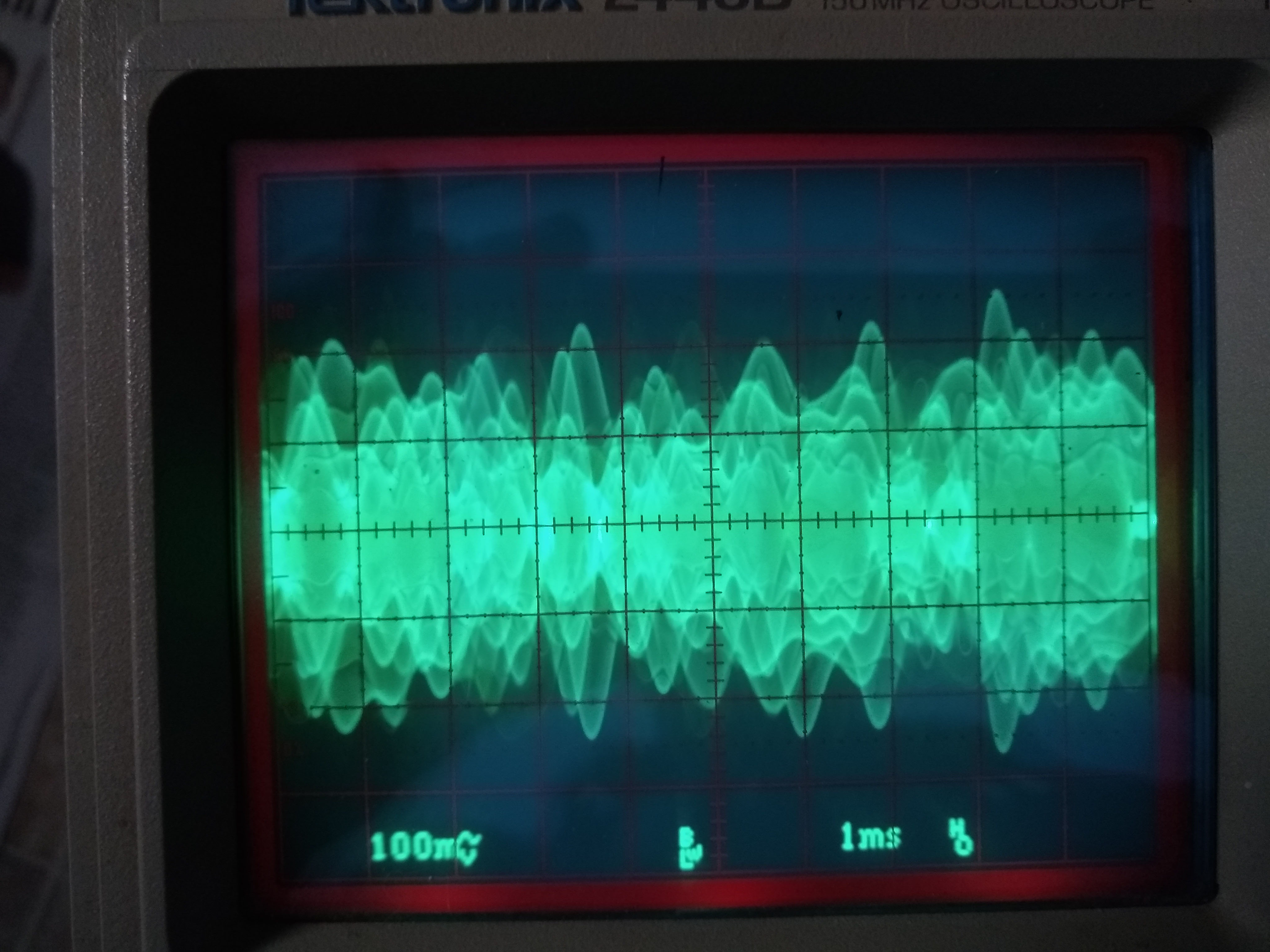
- The 6AU6 1st IF amplifier runs hot, and I had at least one tube fail. An examination of the circuit showed that the 1st IF amplifier was biased for higher quiescent current than the 2nd IF amplifier which is also a 6AU6. The 2nd IF amplifier runs much cooler. The 1st IF has a total of 112 ohms (2x 56 ohms) in the cathode circuit while the 2nd IF has 220 ohms in that circuit. Measurements showed about 1.4 Volts across the 112 ohms in the 1st IF cathode circuit corresponding to 12.5 ma of cathode current. Measurements on the screen grid voltage corresponded to about 2 ma of current, so the plate was at about 10.5 ma or 3.15 watts plate dissipation (with about 300 VDC on the plate). The 6AU6 is rated at 3.5 watts plate dissipation max, so there is not much margin, and in the confined space of the SB-101 chassis, heat buildup might result in failure. I added 56 ohm resistors to each of R104 and R105 in the cathode circuit to raise the total cathode circuit resistance to 224 ohms. The voltage across the 224 ohms was then 2.1 volts or 9.4 ma of cathode current. Allowing for about 2 ma of screen grid current, the plate current was then about 7.4 ma or 2.2 watts of plate dissipation or well within the spec. This modification created imbalance for the S-meter and required adding 200 kohms in parallel with R107 in the screen grid circuit to balance the S-meter. With these changes, the 1st IF runs significantly cooler and appears to have resolved the problems caused by an overheating 1st IF. Why Heathkit configured the 1st IF to run so close to the max is not clear. With these changes, there was still plenty of drive for the TX and there was no significant loss of RX sensitivity. The hot biasing of the 1st IF may have been related to linearity for the TX, but this is not obvious. The hot 1st IF circuit was continued in the HW-101 design also. The scope photo below shows no obvious flat-topping of the signal in TX mode at the output of the 1st IF amplifier under strong audio input in SSB mode.