This unit was purchased in 2018 by KA2C from a local ham. Inspection showed that it appeared complete and should be functional. It was wired for 220 VAC and also had modifications with a softstart module and a new power supply board. The meter’s plastic case inside the chassis was partially melted and deformed due to excessive heat from the meter’s pilot lamp. I decided to modify it for 115 VAC operation and to fix the meter prior to any testing.
Since this unit has over 2000 volts on the finals which is well beyond lethal levels, extreme care is required in repair/testing!!! This includes maintaining a healthy distance during operation/testing with the covers removed, and using a ground connection from the chassis to the 115VAC conduit ground. I did not go near the internal components until the unit was OFF, the power cord removed from the wall outlet, about 1 minute of time was allowed for HV discharge, and a screwdriver was used to short the tube caps to the chassis before proceeding with any operation on the unit, and then double checking that all these steps were completed.
The change to 115 VAC included replacing the power plug, rewiring the power transformer’s 2 primary windings for parallel operation instead of series operation, and replacing the 2 power resistors on the softstart module with 10 ohms instead of 20 ohms resistors.
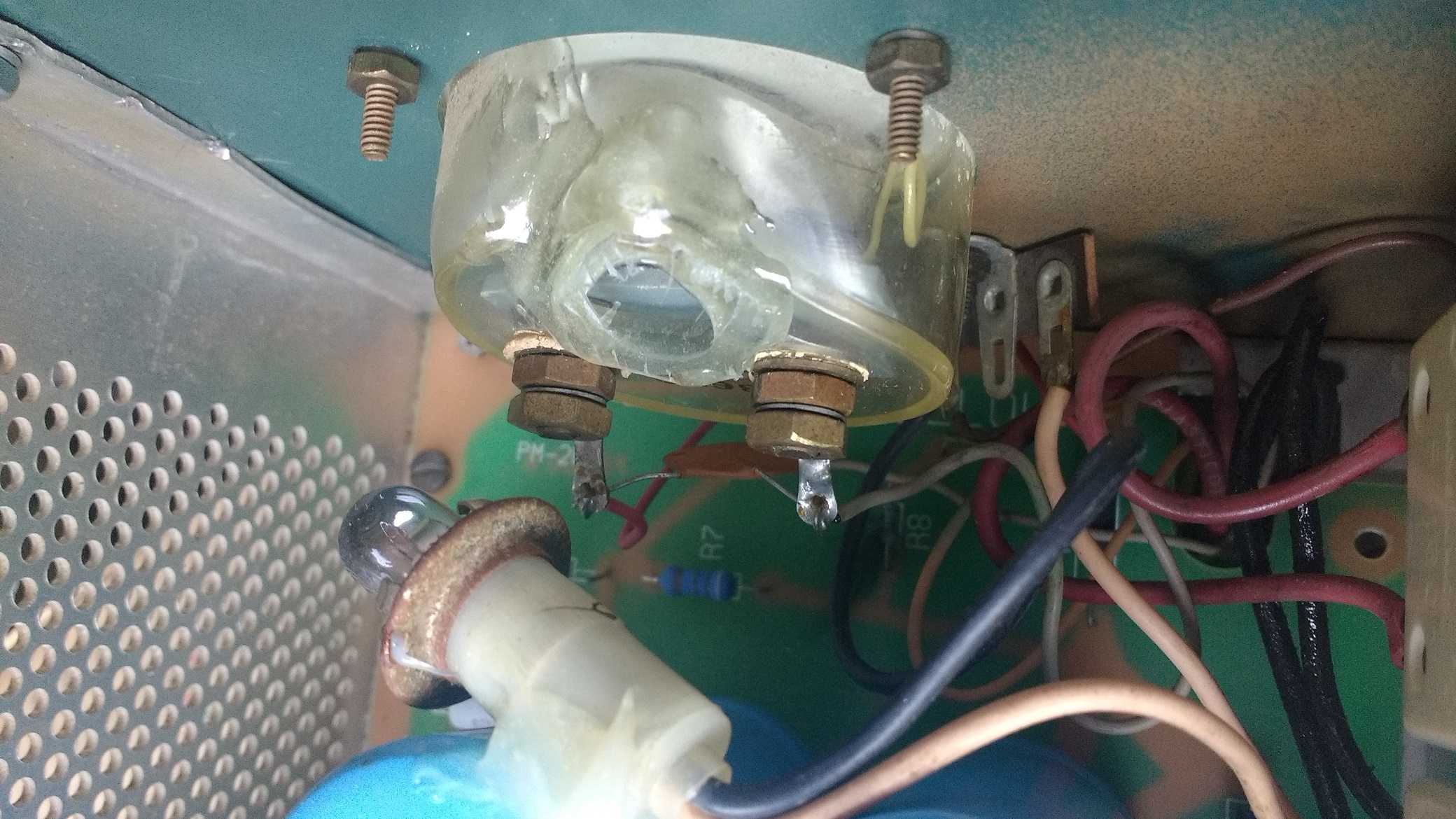
The meter was fixed by removing the pilot lamp and gluing it with epoxy to a filter capacitor on the power supply board. so that it would still light the meter albeit with reduced intensity. The meter’s plastic case was then sealed with a small piece of plastic and epoxy. The meter’s operation was fine and the heat from the pilot lamp was no longer trapped inside the sealed meter.
Initial testing showed that the power output was only about 300 watts. After swapping in a pair of spare tubes that came with the unit, the output power increased to about 600 watts which is reasonable for 115 VAC operation. However, after a few months, those finals also failed, perhaps due to gas leakage and arcing and/or insufficient care in operation. The 572B tubes used in the SB-200 have been out of USA production for many years, and then Russian and more recently Chinese variants have been available. After much reading, I decided to try 572B tubes introduced by DX Engineering in 2016. So far they perform well providing about 600 watts of output. There is a spec sheet for these units showing a max rated plate/anode voltage of only 1250 volts and a max plate dissipation of only 125 watts versus almost 2x these values for legacy USA Cetron tubes. Nevertheless, DX Engineering recommends these tubes for these amplifiers and they at least are working fine with limited operations.
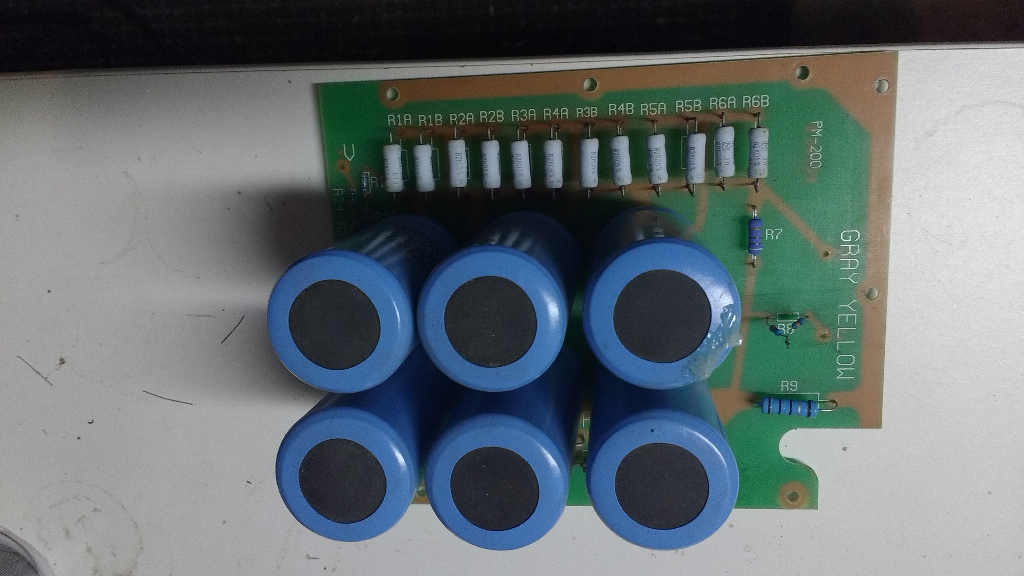
When the 2nd set of tubes failed, they took out the HV power supply. My first concern that the main transformer and/or the meter were damaged proved to not be true, fortunately, and only 3 resistors were blown which were designed to provide some protection in case of HV or tube failure. The 33 Ohm grid resistor was blown on 1 tube, which is known to fail if the grid shorts. The plate current 1 Ohm resistor sensing resistor in series with the HV supply to ground, and the 3.6k resistor in series with the meter for measuring HV also failed. Equivalent modern resistors (carbon film) were readily available at low cost from Ebay sources. The pictures show the blown resistors and fixes, and the final picture is the unit under test (HV at the final caps disconnected for test).
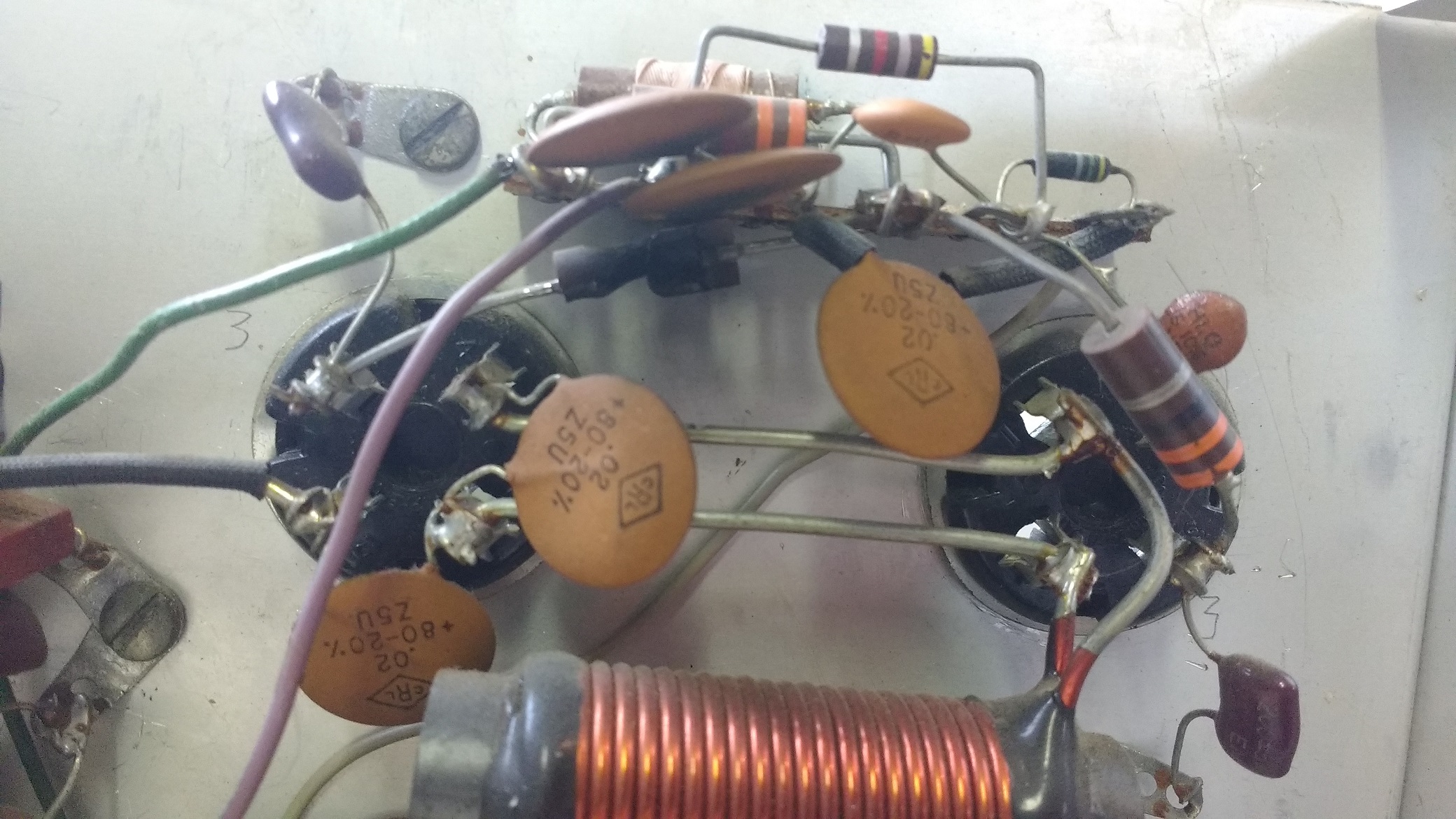
Blown 33 Ohm grid resistor

33 Ohm replacement on one tube and vintage 33 Ohm carbon resistor on the other tube
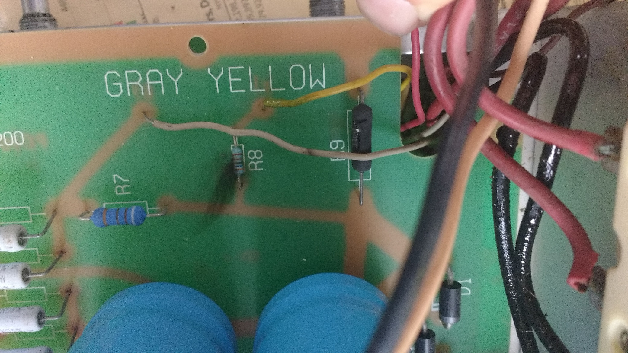
Blown plate current sensing resistors
Fixed plate current sensing resistors
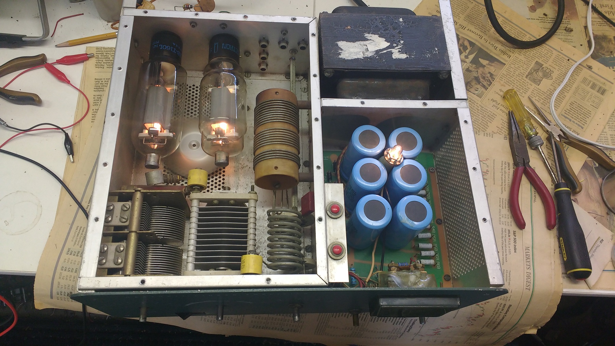
HV under test with plate caps disconnected and pilot lamp out of position