
Restored SB-220 RF amplifier with SB-101 transceiver – The SB-220 appeared in good physical condition when initially obtained, but had not been used in about 20 years and was a bit dirty, so significant restoration would be needed.
Restoration spanned several months and probably 25 to 30 hours of work and included a thorough cleaning, rebuilding the HV capacitor bank, replacing 1 tube, and adding Soft-Start and Soft-Key upgrade kits.
The unit has voltages up to 3000 volts which is lethal, and all work requires careful procedures for safe operation; 1) NO work on the unit and keep proper distance except with the unit unplugged and allowing time for the HV to discharge and checked with a shorting screwdriver, 2) ground the chassis properly; and 3) check everything 2x before proceeding. Do not attempt this kind of work without very good understanding of working with HV.
The SB-220 case is removed by carefully sitting/balancing the rear panel of the unit on a small piece of 2×4 wood (6 to 10 inches long), and then pulling the case up off of the unit (feet need to be removed of course). After removing the top inside cover for the unit, the front panel can be removed after removing the 3 large; tuning, loading, and band selection knobs. The front panel remains attached with wires to the meter switch and meters, so care is required not to damage them.
First steps in restoration after opening the unit:
-pull 3-500Z final tubes
– clean front panel and case with a soft rag and warm soapy water being careful not to get moisture into switches and other components
– lightly oil bearings/bushings, break free, and rotate a number of times each front panel shaft
– clean RF band switch, meter switch and TX/RX relay contacts with contact cleaner – rotate switches a number of times and slide gently a piece of paper between relay contacts to loosen/remove any oxidation
– clean dirt from chassis – use compressed air to clean tuning capacitors
– rewire the power supply for 110VAC operation and replaced the 220VAC power plug with a 110VAC plug
– check the meters for operation using a 50k ohm resistor attached to a 15VDC variable power supply and swing them back and forth a number of times by varying the voltage from min to 10+ VDC – the 200 uA movement meters worked OK
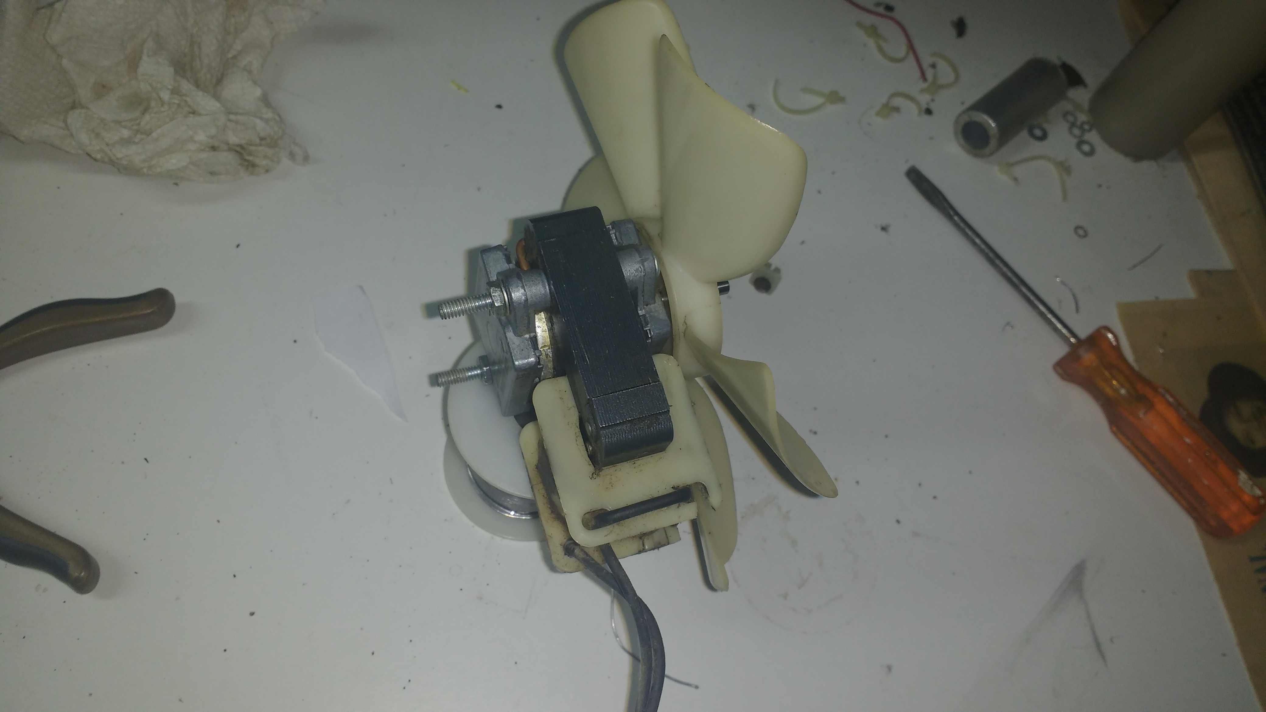
The fan was frozen. The shaft of the armature needed to removed from the 2 bearings, cleaned and lightly oiled to restore proper operation.
With the tubes removed and with other precautions, a first test of the HV power supply was performed with a variac providing only about 25VAC to the unit. With the meter switch set to HV, the meter just barely moved. Using a HV probe on an oscilloscope showed proper AC voltage from the HV transformer given 25VAC into the unit. I then removed the capacitor bank and HV diode board from the unit after desoldering about 10 connecting wires including connections to the HV transformer, front panel and Zener bias diode. Testing showed that the HV diodes and the capacitor bank bleeder resistors appeared OK, but the HV capacitors appeared damaged with small cracks in the base, and the three 4.7 Mohm resistors in series in the HV measurement circuit were very badly out of spec. This indicated that the HV filter capacitors needed replacement as well as the HV measurement resistors. Since the HV diodes and bleeder resistors were OK, I decided not to go with available kits which replace all of these components on a new PCB, but cost over $100. Instead, I found suitable substitution capacitors at 220 uF and 450VDC from Newark Electronics (Manufacturer part #SLP221M450H3P3) with diameter 35 mm to match the size of the openings in the Heathkit original plastic HV capacitor spacers. A total of 8 capacitors are needed. These capacitors were less than $3 each, but tax and shipping added some cost.
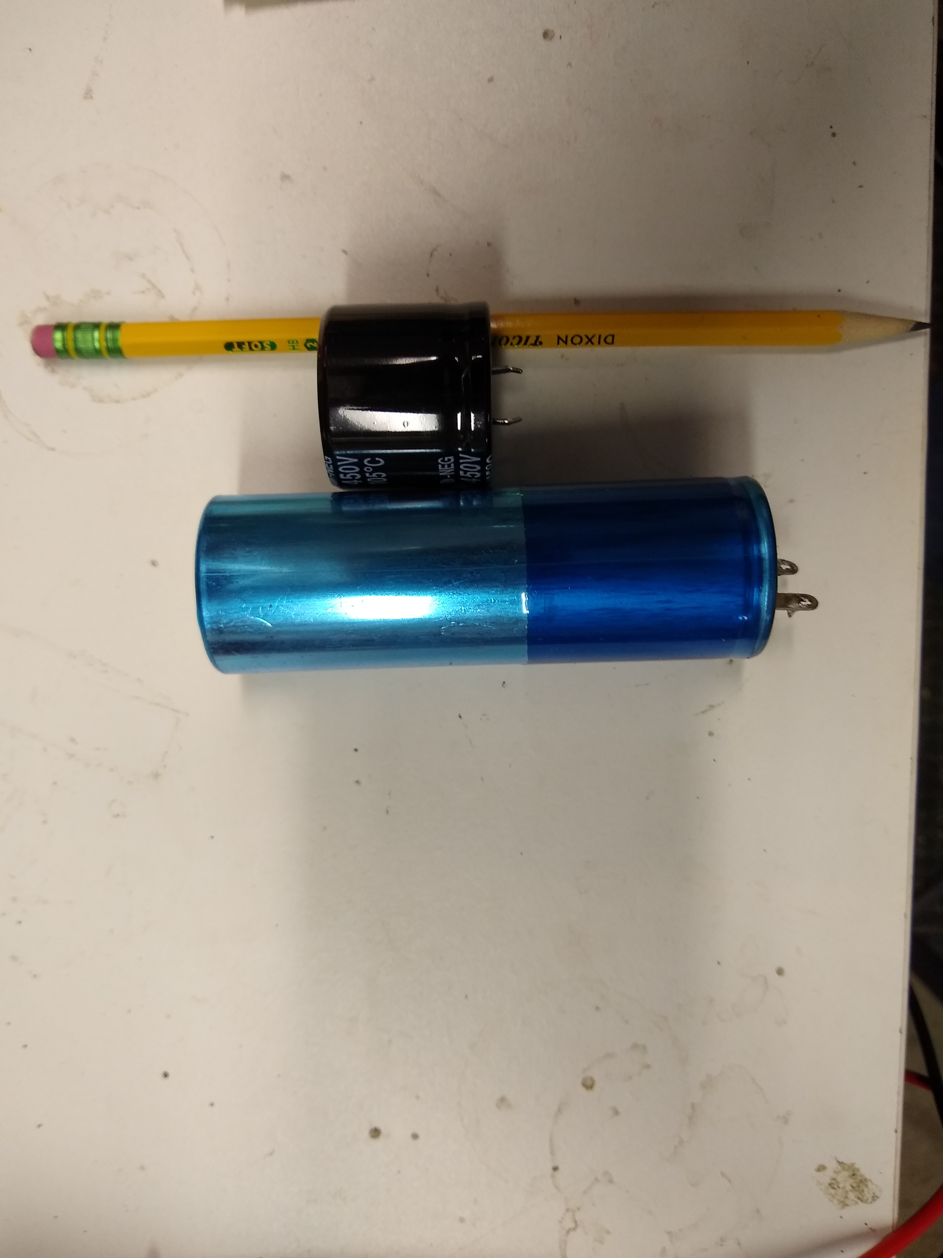
The new capacitors have the same or very close diameter to the old units, but the length is only about 1/4 of the original length.
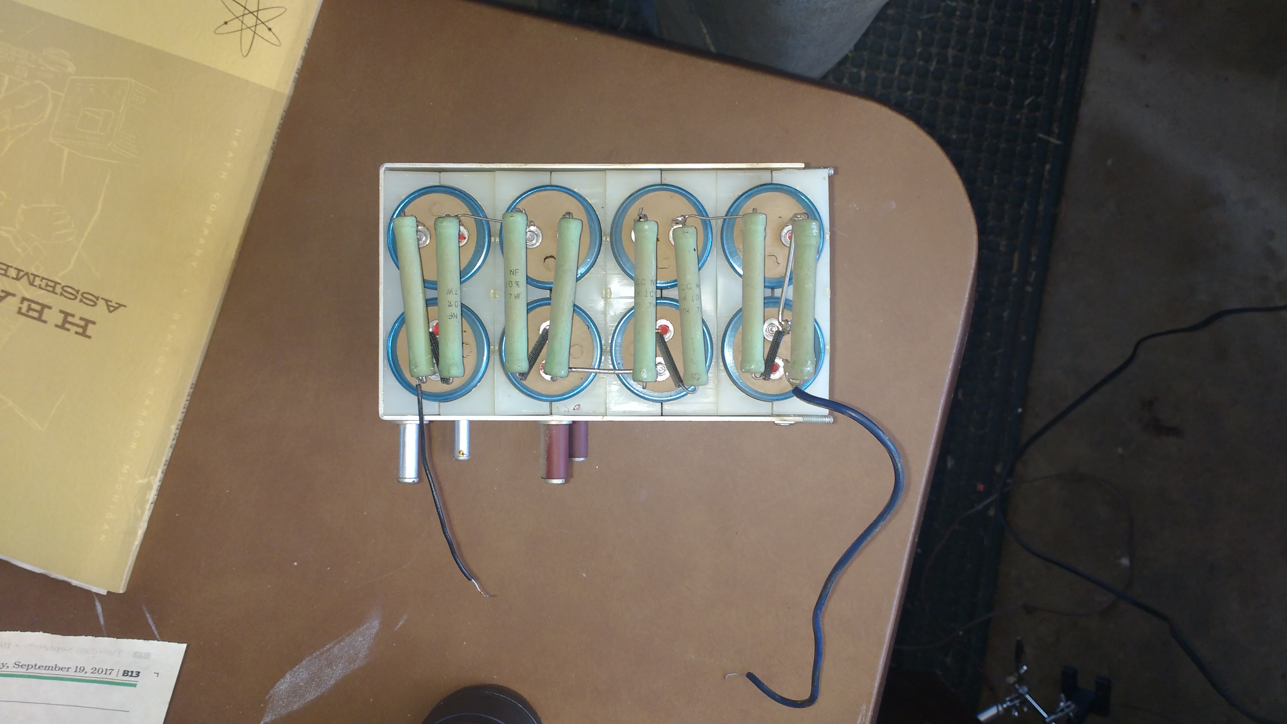
The original capacitor stack
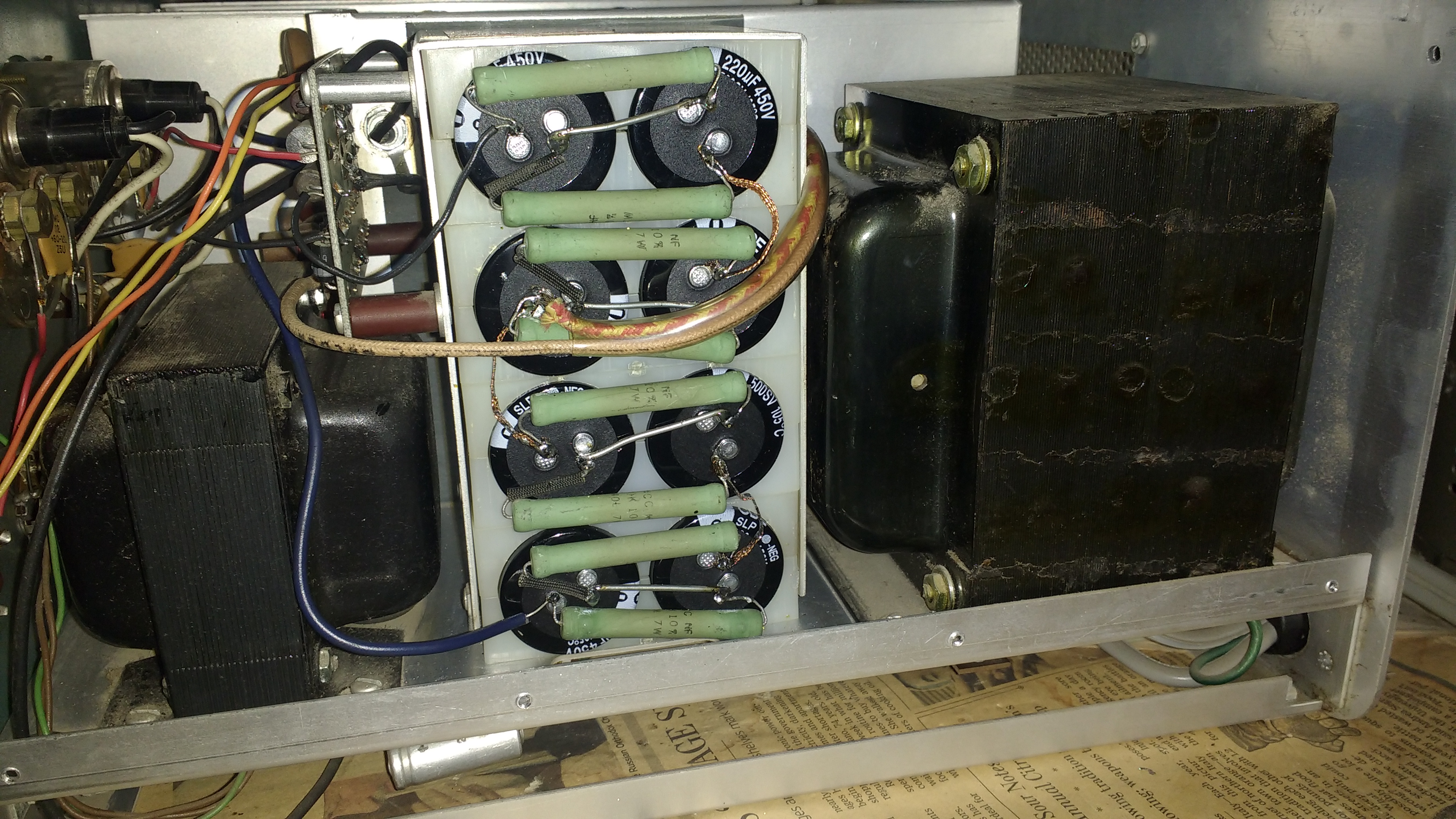
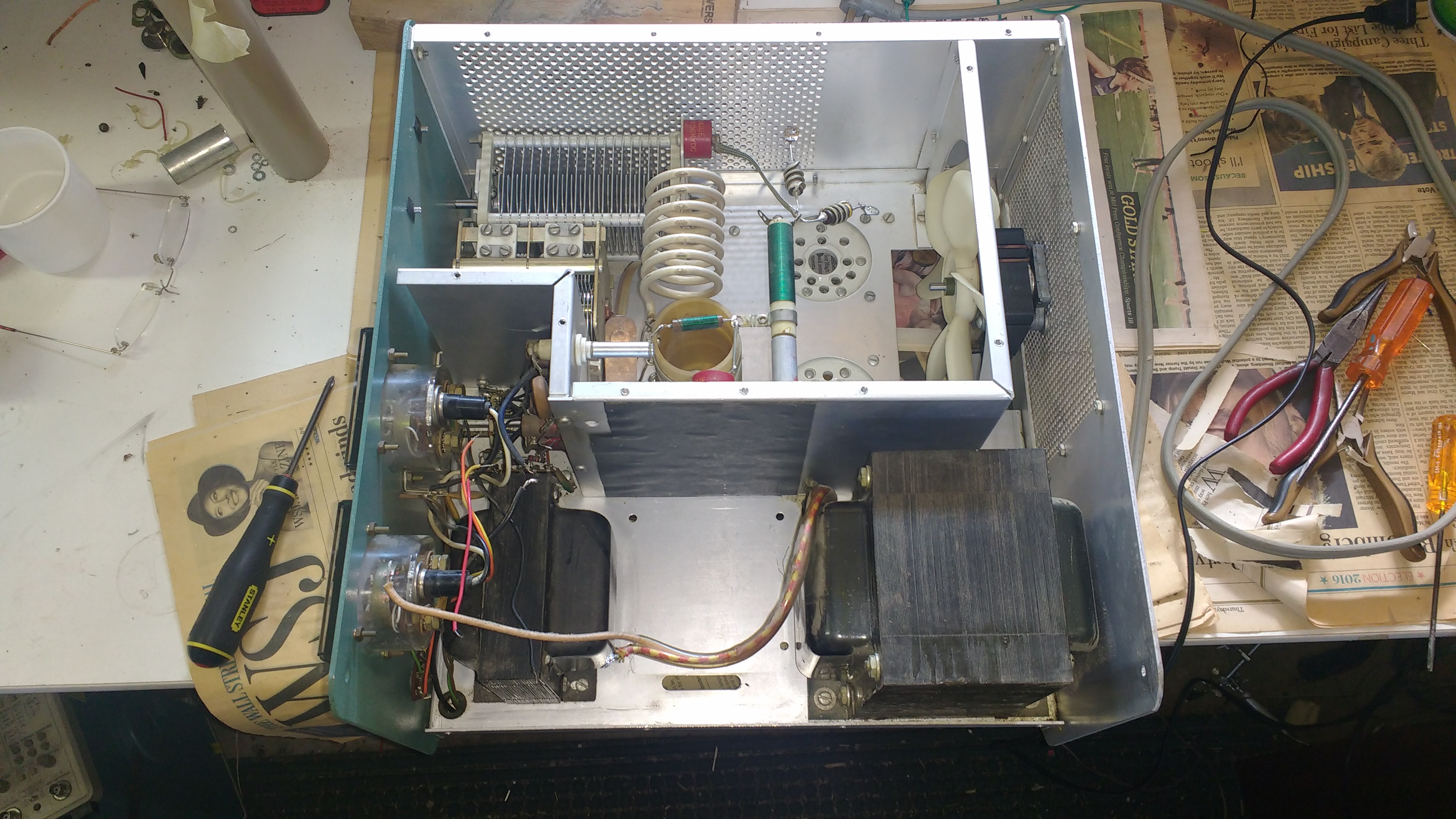
The new capacitor stack installed back into the chassis. This took several hours of careful mechanical and solder work. The reassembly was performed in place in the chassis following the instructions in the manual and moving one bleeder resistor and connecting wire at a time from the old capacitor bank to the new capacitor bank. The new capacitor had connecting leads that were closer than the old capacitors and the new units had snap-in leads instead of the original solder lug leads. These differences required some care in reassembly. Then the three 4.7 Mohm resistors on the HV diode PCB were replaced with units obtained on Ebay. After reconnecting the HV transformer and front panel component connecting wires and visually checking everything several times, the unit was tested on the variac at 25VAC. The HV supply showed about 600 VDC on the meter. I then brought the variac up to full 110VAC in several steps. Finally, I switched the mode from CW/Tune to SSB to check the HV supply at max voltage and it showed near 3000 VDC unloaded and the circuits all appeared OK.
The next steps were to test the 5VAC filament supply; the 110VDC relay/bias supply; and the TX/RX relay operation with an external switch connected to the relay phono-plug with full power to the unit. These all appeared fine.
The next steps were to install the Soft-Start and Soft-Key upgrade kits by Harbach for the SB-220.

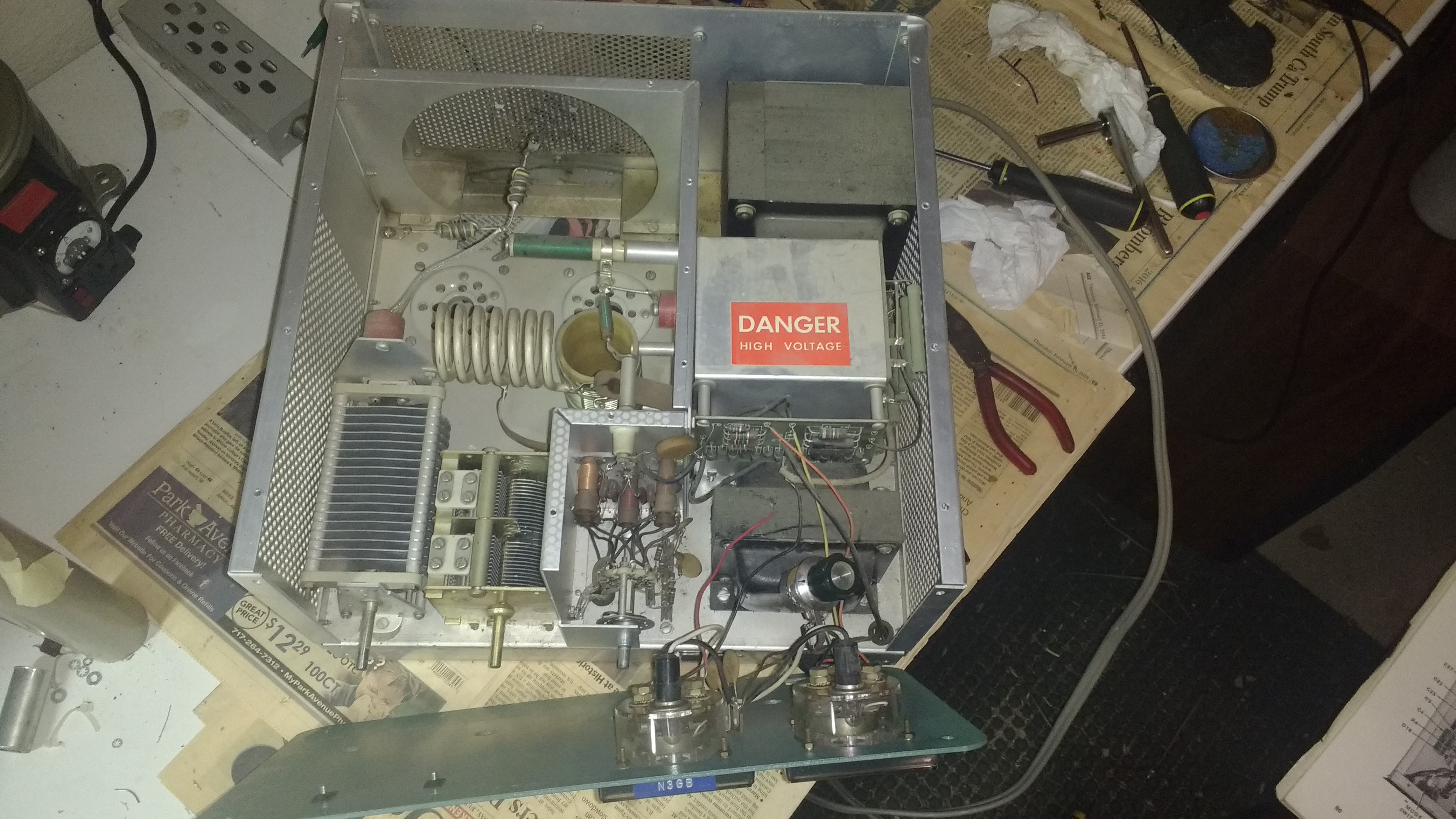
Chassis bottom prior installing Soft-Start and Soft-Key kits
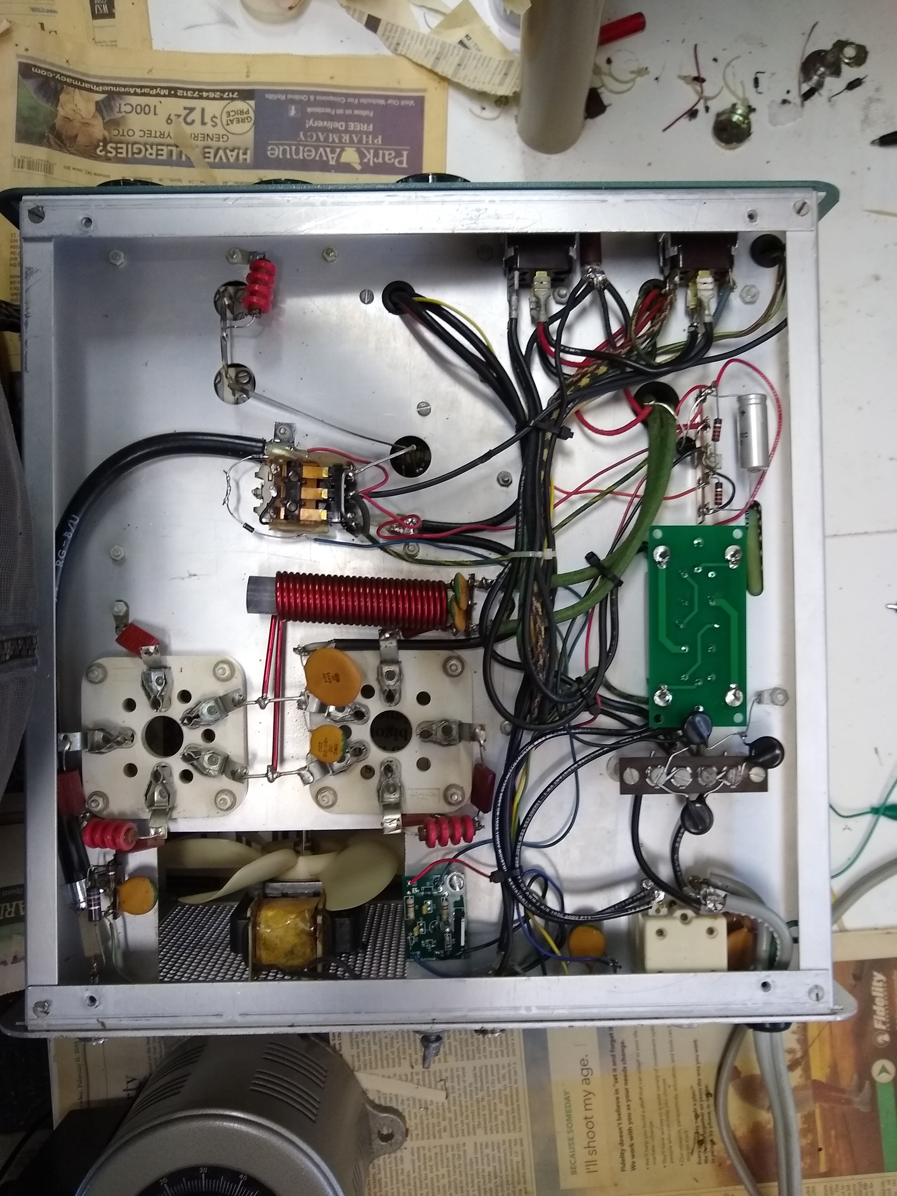
The Soft-Key PCB is located in the bottom center, and the Soft-Start PCB is located in the center right. The Soft-Key PCB has sensitive transistors/diodes and fine traces on the PCB, so using a low wattage soldering iron with a fine point is necessary during PCB assembly, while a larger soldering point is needed for the solder lug connections and a few large connections on the Soft-Start PCB. After allowing several days for the glue attaching the Soft-Start kit to the chassis to dry, I tested the unit, and both upgrade kits functioned as expected.
The next step was to install the tubes with the plates NOT connected to the HV and test the filaments. The tubes were original Eimac 3-500Z’s. Unfortunately one of the tubes showed that gas had leaked into the tube, and it clearly would not work and would short the HV if attempted, but one tube appeared fine. I then pulled the bad tube and connected the HV to the plate of the tube that appeared OK. Using the variac, I started the HV test on the tube at about 2/3 to 3/4 max to provide sufficient voltage to partially heat the filament, and it appeared fine with the unit in CW/Tune mode. After bringing the supply voltage to full 110VAC, the tube still appeared fine, so I brought the HV to a full 3000 VDC in SSB mode. The next step was to trigger the TX/RX relay after returning the CW/Tune mode, and the plate current showed about 60 ma as expected which suggested the tube was good.
Original 3-500Z tubes are very hard to find today and may be risky due to their age. It appears RF-Parts is about the only USA source of Chinese manufactured 3-500Z tubes, and they are priced at over $200 each. I decided to pair the original Eimac 3-500Z with a new Chinese 3-500Z from RF-Parts. After obtaining the new tube, and testing the filament, I connected the HV to the plate, and it appeared OK. Testing TX mode with the TX/RX relay showed a total plate current of about 120 ma as expected, and that in spite of using non-matched tubes from different manufacturers, the idle plate currents of the 2 tubes were reasonably matched.
The next step was to actually apply RF drive and test the SB-220 under normal operating conditions. Using the SB-101 for RF input, I slowly brought up the RF input to the SB-220, tuning both units at 25 to 50% RF power levels before going to full power. I found that 40 meters was weak on output power while the other bands appeared OK. After some investigation, I concluded it must be the input tuned circuit. Heathkit provided the input tuned Pi networks as fixed components. Apparently they pre-tuned the slug-tuned inductors with a tuning jig and then glued the slugs in place. But variation in the fixed capacitors and in the tuned inductor might be an issue. Unfortunately the input tuned circuits were located behind the front panel and in close proximity to the HV power supply. So, these were not easy to adjust. After loosing the front panel, I carefully broke the glue on the 40 meter input coil slug with a metal Allen wrench, making sure the wrench was fully extended through the tuning slug for maximum force. By gently rocking the wrench back and forth the glue was broken without damage to the slug, and then I rotated it +- about 3 turns to clean out the glue. Then I switched to a plastic RF slug tuning tool. After returning the slug to its original position, I tested 40 meter power again, and then powered the unit off (and unplugged it) several times while moving the slug 1/2 to 1 turn per cycle to safely optimize the circuit. For each test, the front panel was secured in place with the nut and washer on the RF band switch to make sure nothing was shorted during operation.
Final testing showed about 800 watts output in CW/Tune mode for 80 to 15 meters and slightly lower on 10 meters as expected. SSB mode showed about 1000 watts peak output. These levels are a bit low for the SB-220, but this is with 110VAC input after almost 500 feet of distribution cable to the shack. Also, my other SB-220 shows identical performance under these limitations.