Adding 160 meters to my Heathkit SB-220 RF power amplifier
The first step to modify my Heathkit SB-220 to add 160 meters was to research existing articles on such upgrades. Some hams did such modifications as far back as over 40 years ago in the 1970’s. I found:
- http://www.somis.org/add-160m.html
- https://www.pestingers.net/pdfs/heathkit-radios/sb220-complete-book-of-mods-1987-kozlarek-wa2sqq.pdf
- http://www.radiomanual.info/schemi/ACC_PA/Heathkit_SB-220_160_meter_adding_1979.pdf
One key point from these articles was that adding a new 160 meters tuned input circuit was not necessary. Instead the 80 meters tuned input circuit could be used which acts as a low-pass filter and hence passes 160 meters signals. But it is necessary to add an additional 160 meters tank inductor and additional loading and tuning fixed capacitors to properly tune the amplifier output pi-network to 160 meters with the proper input and output impedances. It is also necessary to replace the filament choke and plate choke with new components with about 2x the inductance compared to the original parts to operate efficiently and safely on 160 meters. In this design, the existing SB-220 band switch is set to 80 meters for 160 meters operation, and 3 vacuum relays reconfigure the output pi-network for 160 meters operation controlled by a small toggle switch added on the front panel.
The first step was to replace the filament choke. After opening up the unit, I removed the tubes before proceeding. The new higher value choke designed to support 160 meters from Ameritron is larger than the original choke, but there is plenty of room to install it. It does result in slightly longer leads to connect the choke to the filaments. I simply unwound 1 to 2 turns of the old choke on the filament side of the choke after disconnecting the old choke from the transformer leads and used those wires to connect to the new choke. Since those wires and the choke wires are very large, I kept them straight at the connections, and wound copper braid around those wires to make a secure connection prior to soldering. Two additional 0.1 uF 1 kV filament bypass capacitors were also added in this step. Once the filament choke & bypass capacitors were installed. I replaced the tubes and performed a filament test & confirmed that the hi-voltage supply was still fine.

The old filament choke
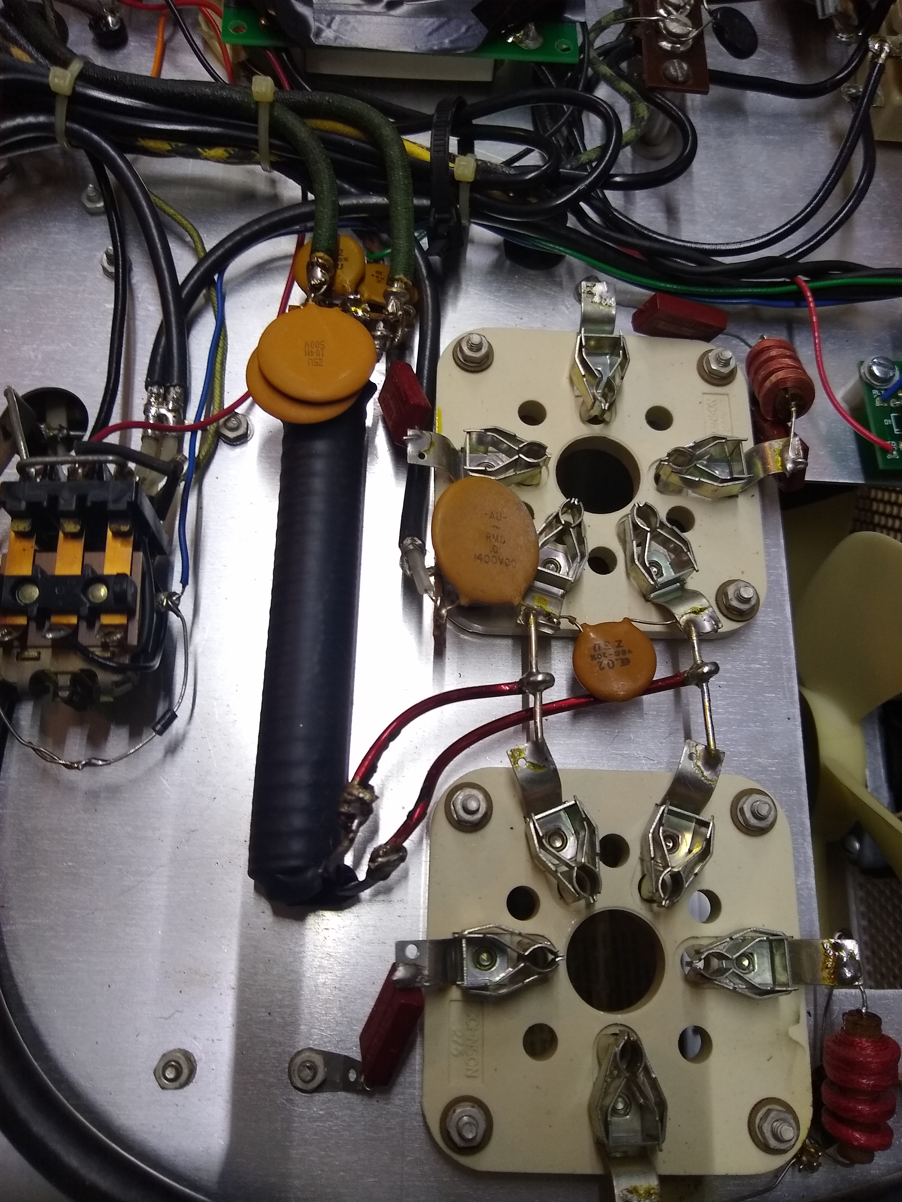
The new filament choke and 2 additional bypass caps
The second step was to replace the plate choke. The new plate choke is much larger than the old plate choke in both diameter and length, but when properly mounted to the same spot as the original choke, it fits fine although removing and replacing the tubes has less margin to maneuver. Removing the old choke involves removing the mounting bolt and replacing it with a ¾” ¼-20 bolt. The mounting bolt sits horizontally attached to the sheet metal between the RF compartment and the HV capacitor bank. Fortunately it sits right on the corner of the HV capacitor bank. I was able to loosen 3 of the bolts holding the capacitor bank to the chassis and move it a bit more than ¼ inch which was enough to remove the old bolt and install the new bolt. This also required removing the sheet metal on the outside of the high voltage compartment to provide better access to the area to move the HV capacitor bank slightly and then restore it to its original place. By doing this, it was not necessary to disconnect any wires in the high voltage compartment. Reconnecting the 2 ends of the RF choke required short lengths of new additional wire to connect each end. Once everything was reinstalled, a detailed visual inspection was done, and then the tubes were replaced to perform filament and high voltage tests as shown by the HV meter.

The old plate choke
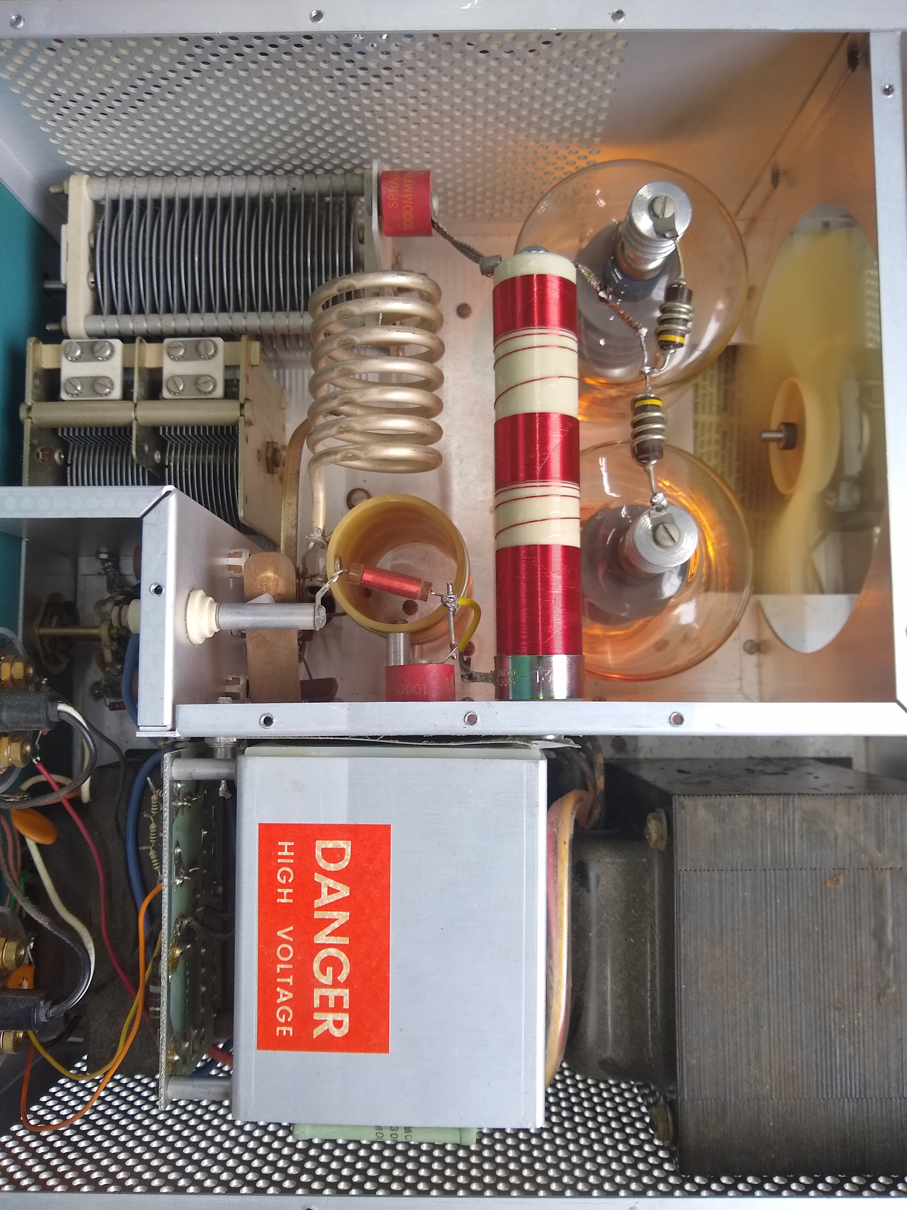
The new plate choke
The third step was to install 2 small DPDT toggle switches on the bottom of the front panel under the 3 large knobs and to install the jack for the external 12VDC power plug. The first DPDT switch is wired to select 80-10 meters or normal operation in the first position (in this position the vacuum relay is closed which shorts the 160 meters tank coil by proving 12 VDC to its coil) and 160 meters in the second position (in this position the 2 vacuum relays are closed which add the HV RF capacitors to the loading and tuning capacitor circuits). The second DPDT switch adds the standby function, and in the operate position it connects the external relay control wire to the relay control circuit. This step required drilling 2 holes in the front panel and 1 hole in the rear panel. The area around where the drill bit penetrated inside the chassis was surrounded with painters tape to collect any metal fragments from the drilling. All metal fragments were carefully cleaned up and the entire chassis was examined top and bottom for any possible loose metal fragments. RF Bypass capacitors of 33 nF and rated at 500 volts were added at the 5.5 mm by 2.1mm jack for the external 12 VDC power plug and at the control wire input to the soft TX/RX relay board due to the long wires added to support the standby function.
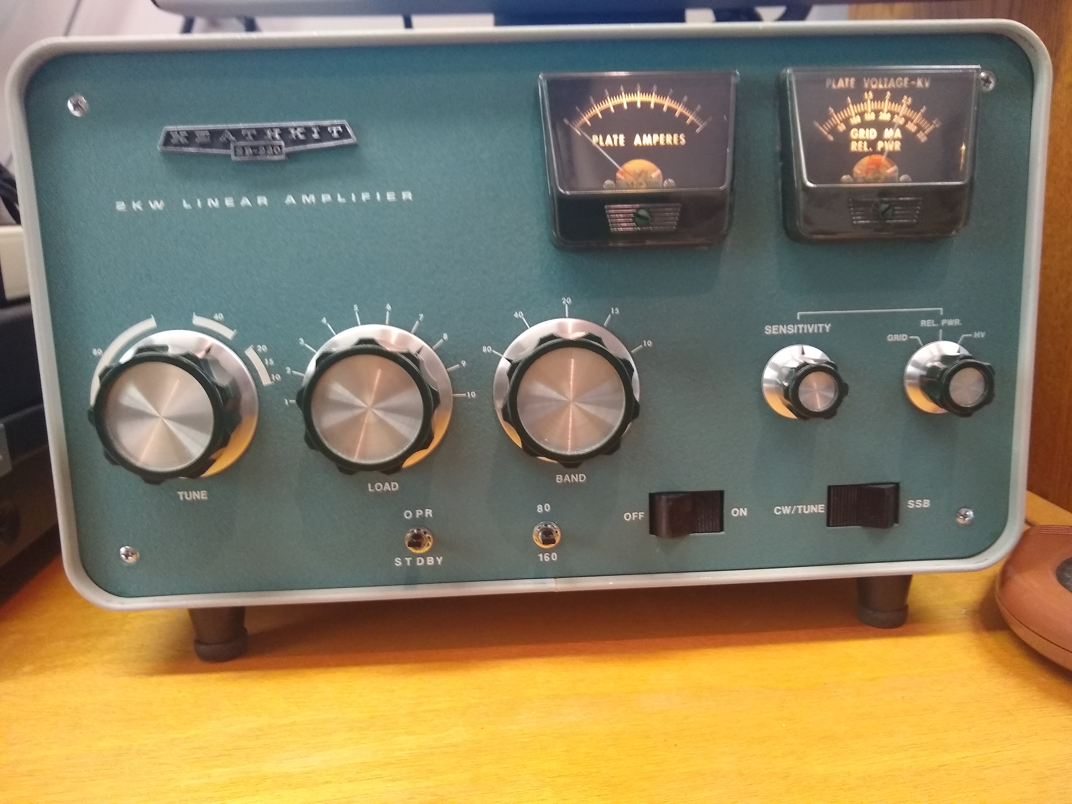
The front panel toggle switches for Standby and 160 meters
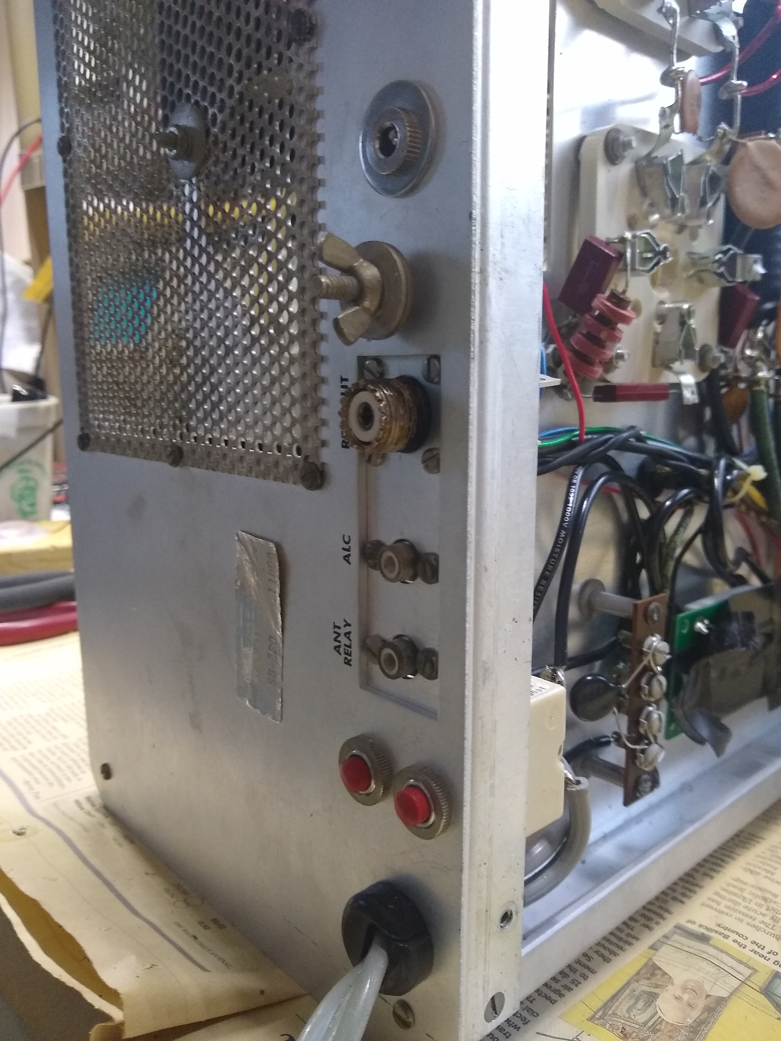
The rear panel jack for 12 VDC near the top of the picture

Using painters tape to catch metal fragments during panel drilling
In the fourth and final step, the 160 meters tank coil, additional loading and tuning fixed door knob capacitors were added along with the 3 vacuum relays to switch them in/out of the circuit depending on the selected band. I used 1/8″ plexiglass sheet and cut 2 pieces at about 2.5” x 3.5” to create 2 mounting boards. The first board was designed to hold two vacuum relays and the associated tuning and loading caps connect to one side of this board. The second board was designed to hold one vacuum relay and the 160 meters coil. The plexiglass is readily available and easy to cut/drill, but is subject to melting during soldering, so some care is required to avoid problems. The two vacuum relays boards are mounted on top of each other with the first board mounted to the left side sheet metal in the RF compartment (as viewed from the amplifier front), and the second board then mounts to the first board. The 160 meters tank coil is then attached to the second vacuum relay board.
To prepare for the final major step, the existing 80 meters coil must be disconnected from the RF switch which is at the bottom of the tank coil and hard to reach. With the tubes removed and using a small metal rod to push on the wire while loosening the solder joint of the wire at the coil connection, I was able to disconnect the short wire. I used a 40 watt iron for this work. This also leaves the existing short wire still connected to the 80 meters connection on the RF switch which is convenient to connect the new 160 meters tank coil in this hard to reach area. Other preparation work included cutting the 2 plexiglass boards and drilling holes for the vacuum relays contacts and then for the 4 mounting nylon spacers on each board. The vacuum relays were attached to the prepared plexiglass boards with a small drop of epoxy on each end mount.
On the first board the 2 vacuum relays are mounted horizontally with one above the other. The relay coils and contacts close to the front panel are all wired to ground but with 3 different wires to spread the RF currents across wires as well as separate the RF current from the control wire current. The relay coils are connected to the chassis ground at the corner of the front panel and the side panel using typical hookup wire. The contacts on the first relay are connected in parallel and connected to one heavy ground screw on the top side of the variable loading capacitor, and the contacts on the second relay are connected in parallel to the other nearby heavy ground screw on the top side of the variable loading capacitor. I used #14 7-strand copper antenna wire for all of the high power tank connections. Also, each vacuum relay is a DPST normally open switch, and the 2 contacts are wired in parallel to increase the current capability of the relay. At the vacuum relays, the 7-strand wire was pulled apart into 2 parts and connected to the dual relay contacts which are next to each other to wire the relay contacts in parallel to achieve good RF current performance. The door knob RF capacitors are mounted on the rear side of the plexiglass board and connect to the relay contacts on one side. For the 160 meters tuning doorknob RF capacitor (light green in the picture), the hot side of the capacitor connects and mounts to the hot side of the variable tuning capacitor which is nearby, and for the loading capacitor (red in the picture) a wire runs down to a spare screw on the hot side of the variable loading capacitor.
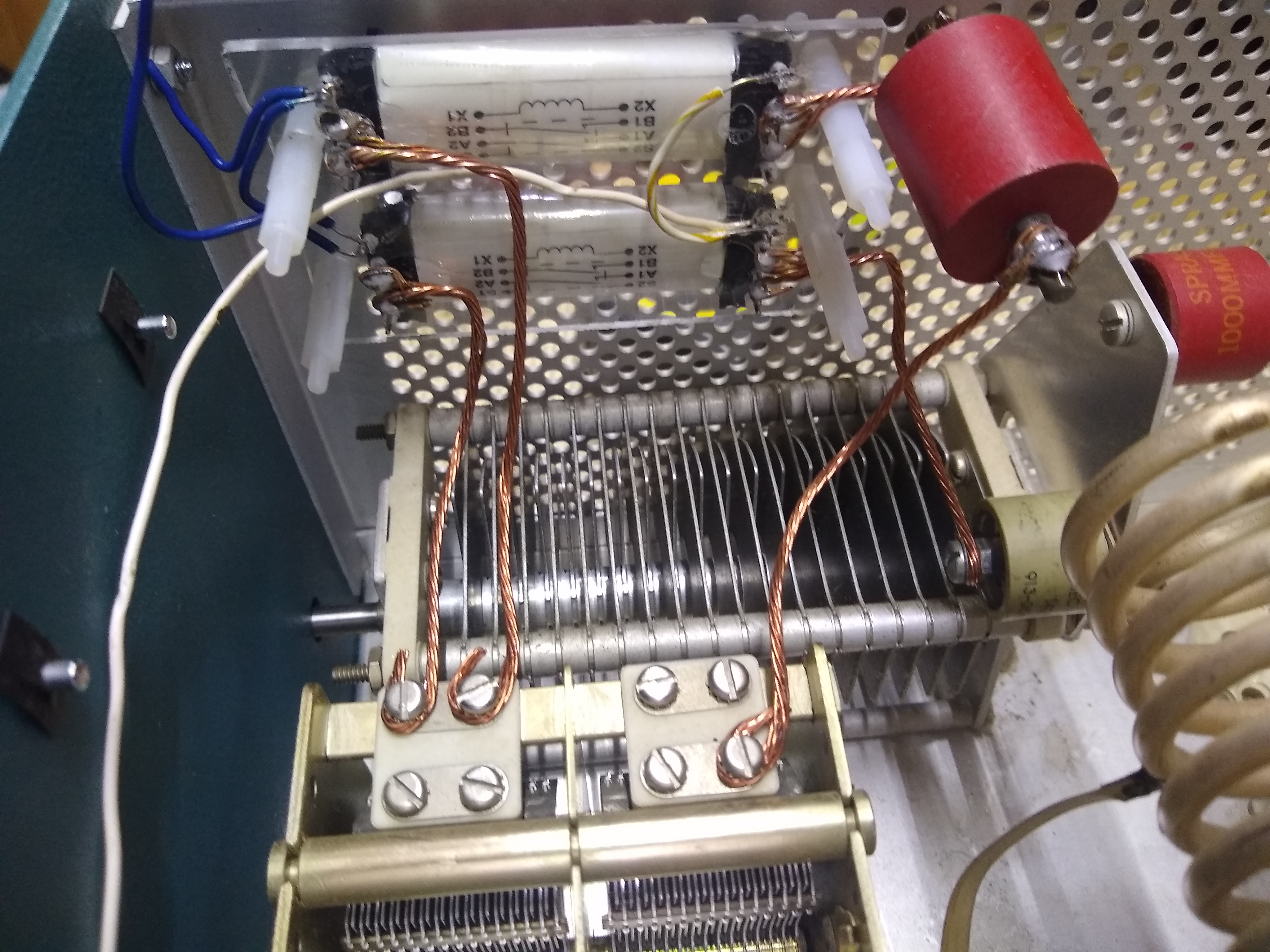
The first vacuum relay board installed with tuning and loading caps for 160 meters.
Once the first board was installed and fully connected. I first plugged in the external 12 VDC power plug (without plugging in the main power supply!!) and tested the vacuum relay operations with an ohm meter. Once the vacuum relay operation was confirmed and after further visual inspections, I also retested the high voltage power supply and the RX/TX relay operation.
On the second board, the vacuum switch is also mounted horizontally on the board. It is important to achieve a fairly short connection for 80 meters when this switch shorts out the 160 meters coil and connects the 80 meters coil directly to the RF switch. The loading coil is also mounted horizontally. One wire for the coil runs from near the front panel back across the coil and then down to the chassis to connect to the bottom of the 80 meters coil. The other end of the coil also runs down to the chassis and connects to the 80 meters switch position. The wire runs connecting the 160 meters coil are a bit long and awkward and needed to be carefully shaped to maintain good spacing to all the nearby high power/voltage tank circuit components. These wires were actually part of the raw coil which was 2″ in diameter with 8 TPI and cut to have 28 remaining turns to achieve 17 to 18 uH of inductance. After installing the second vacuum relay board and 160 meters coil, I tested the vacuum relay operation with an ohm meter before making the final connection of the vacuum relay to one side of the coil (since the coil continuously shorts the circuit for DC). This test could also be done with the relay fully connected using an inductance meter.
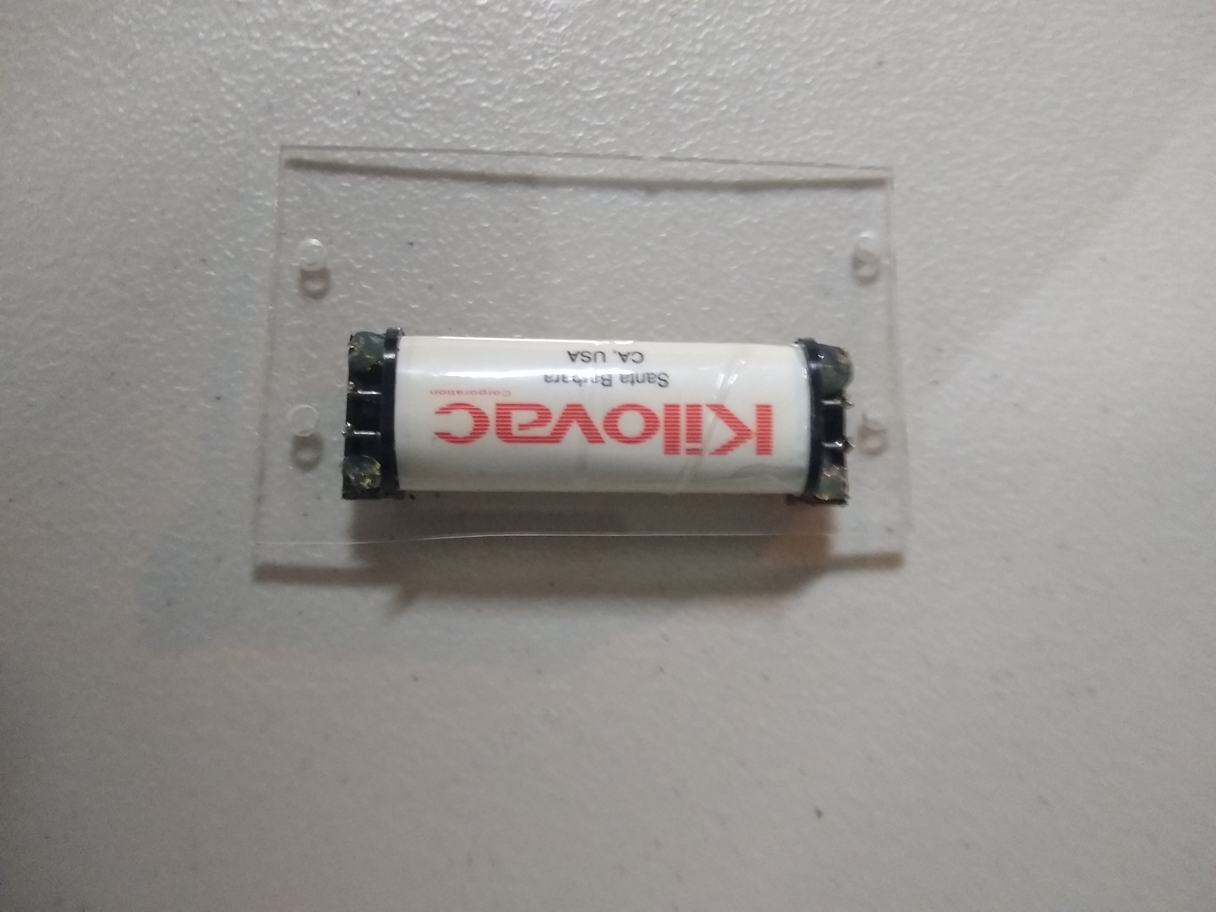
MFJ Kilovac DPST vacuum relay mounted on plexiglass for the second board with epoxy and prepared for installation as the 160 meters shorting switch

The second vacuum relay board installed on top of the first board with the 160 meters tank coil – notice the high voltage copper shorting strap in the lower part of the picture is temporarily disabled with a blocking nylon spacer
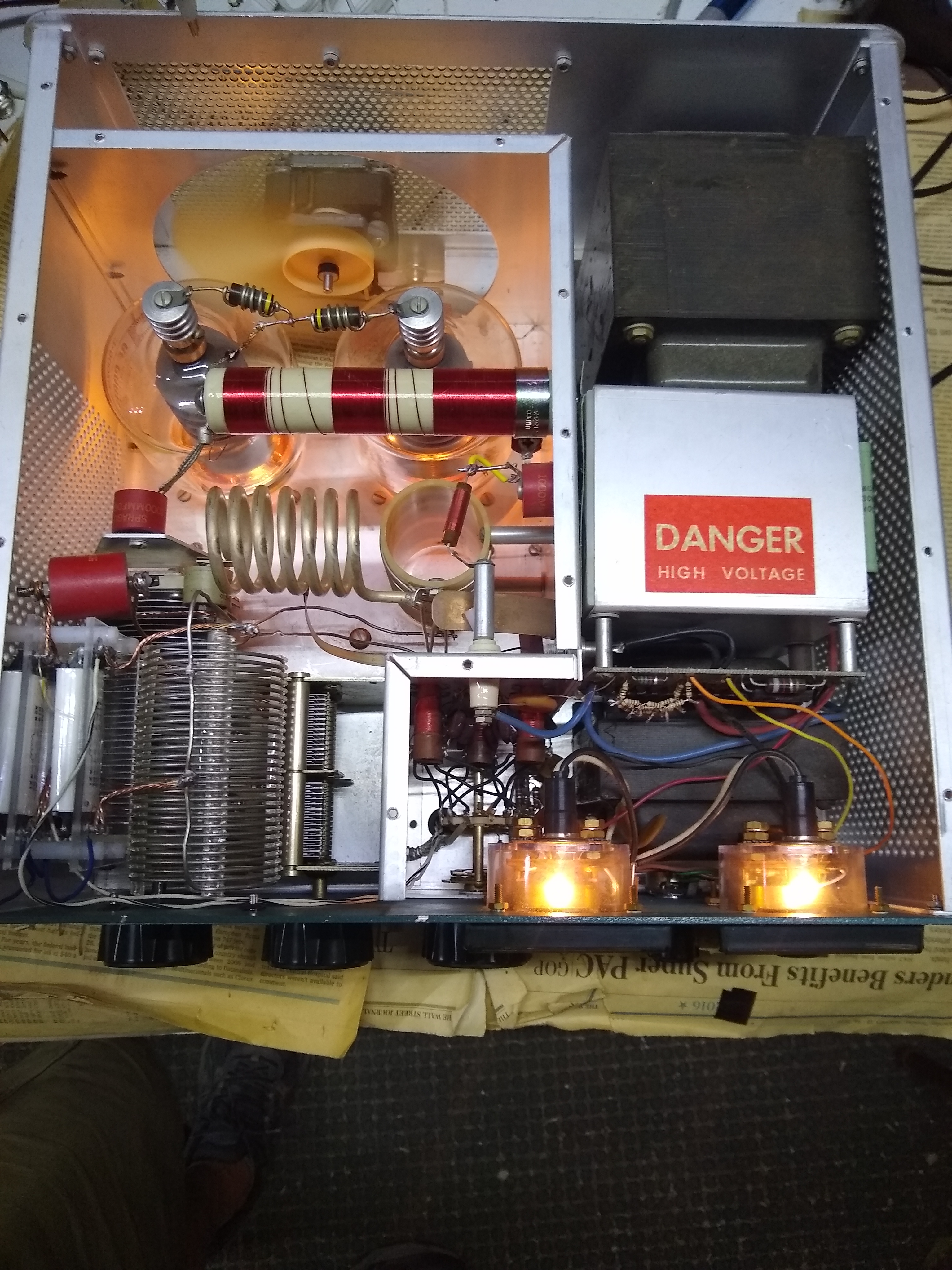
Final view of the amplifier top – control wires for the vacuum relays are seen against the front panel and route to the chassis feedthrough in the RF input tuned circuit area and then to the front panel toggle control switch beneath in the chassis bottom.
Testing then proceeded with reconfirming the high voltage operation was OK and that the RX/TX relay operated OK. After reinstalling the tubes, testing proceeded again with filament; high voltage; RX/TX relay; and vacuum relay operation by audible clicks (I avoided coming anywhere near the tank or any other part of the amplifier except the front panel switches with the high voltage powered ON). Then it was time to proceed to testing with RF drive and measured RF output.
For final testing with RF drive, I used my FT-950 and a 1 kW dummy load. I started on 20 meters where the new circuits are not active, and with only 25 watts of drive. Operation was fine, so I increased drive and was able to tune the amplifier to achieve about 800 watts of output power in CW, which matched performance before modifications. I noticed that the tuning capacitor resonance point moved up slightly in position which probably results from additional stray capacitance on the tuning capacitor. Then I moved to 80 meters which tests the shorting vacuum relay on the 160 meters coil. Operation on 80 meters also matched earlier performance, but again the tuned point moved up in this case probably dominated by the additional wire lengths in the 80 meters tank coil to connect to the 160 meters tank coil and shorting vacuum relay. Testing for 160 meters was the last step, and operation was fine. I found it was important to run the auto-tune capability of the FT-950 rig in 160 meters with the amplifier ON to achieve a good match into the amplifier input and to avoid the FT-950 auto limiting output power. During 160 meters operation, the input circuit continues to use the 80 meters input filter, which acts as a low-pass filter, but provides poorer matching on 160 meters to 50 ohms.
With the SB-220 in CW mode, the following results were achieved:
Band Watts output I plate V plate
160 725 0.57 1950
80 850 0.63 1950
40 900 0.65 1900
20 800 0.54 1950
15 850 0.64 1900
10 800 0.62 1900
The input drive was 100 watts in all cases. The highest output is on 40 meters with 900 watts output and 1235 watts input or 72% efficiency. The Heathkit manual rates the SB-220 at 1000 watts maximum CW input with 2000 V on the plate and 0.5 Amp on the plate, so about 750 watts output maximum. The power varied between 800 and 900 watts output on 80 through 10 meters, but is 725 watts on 160 meters. The slightly lower power on 160 meters may be due to a number of factors including higher losses in the input circuit and higher losses in the grid and plate chokes which are operating near the edge of their capability and higher losses in the tank due to the 160 meters coil and other added circuits. Overall the results are very happy from my point of view.
Parts:
- New Plate RF choke – MFJ plate choke is $24.95 = Ameritron 10-15197
- New Filament choke – MFJ filament choke is $20 = Ameritorn 10-15115-1
- 2x 0.1 x 1 Kv ceramic disc capacitors for additional filament bypass – Ebay
- 160 meters Coil – Need ~ 17.5 uH – use 2” coil with 28 turns at 8 TPI or 3.5” of coil – Hamfest buy
- 3 High voltage relays for Pi-network input circuit Vacuum relays from MFJ = Kilovac DPSTparts – $20 each
- 2 small DPDT toggle switches for the front panel – Hamfest buy
- 12 VDC 1A power plug – Amazon
- Jack for 12 VDC for the rear panel – Amazon
- 500 pF door knob RF cap > 5 KV – Hamfest buy
- 150 pF door knob RF cap > 5 KV – Hamfest buy
- 12” x 12” sheet of 1/8’ plexiglass to make mounts for the vacuum relays, RF caps and Coil – Ebay
- A kit of plastic standoffs – Ebay