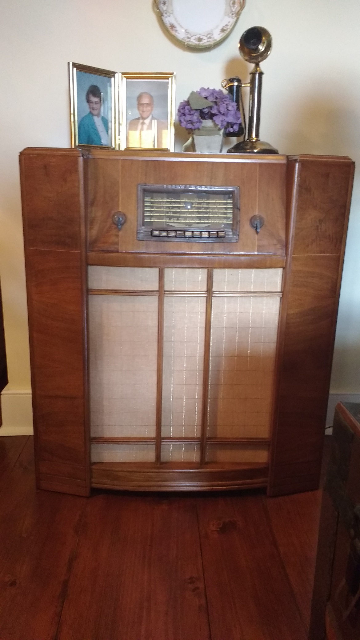
This is a Sears 1940 Silvertone Console radio – an old ad says that it looks like a $100 radio – Grandma Lila Myers had it for many years in a bedroom in the old farmhouse – KA2C came into possession of it about 1975 – later the cabinet was refinished and the grill clothe replaced – more recently a failed resistor that went open was replaced (a common failure mode for vintage carbon resistors) – a small modification was to add a B+ filter choke and additional B+ filter capacitor to reduce AC hum – this radio used an electromagnetic speaker (as opposed to modern permanent magnet speakers) in which the DC speaker magnet winding doubled as a power supply choke and made some modest sacrifice in hum – this design also had 250 volts DC going through one of the speaker coils (not up to modern safety standards!) – with an external antenna and a ground the AM and SW reception is fairly good and the audio is quite good for the vintage – this 1940 radio included an original auxiliary phono input jack for early TV or phonograph selection since the audio subsystem was a significant capability for the day
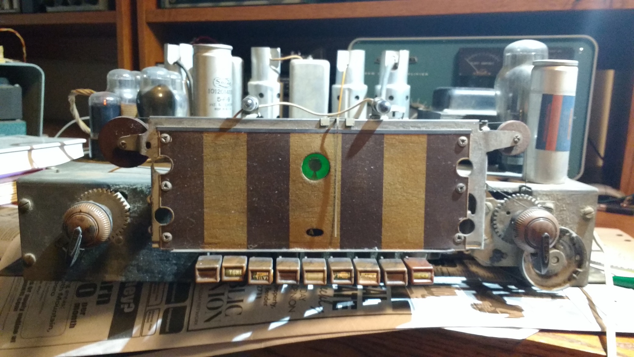
The chassis with the tuning eye tube in the middle of the dial
The radio has 11 tubes including the tuning eye tube in the front, the rectifier tube near the power transformer, RF/IF tubes along the back of the chassis near the 2 IF transformers and push-pull audio tubes clustered in the upper left – this was not an inexpensive design like the “All-American 5 tube” designs with no power transformer – The audio amplifier starts with a unity gain inverting stage, then 2 tubes in push-pull as drivers, and 2 tubes in push-pull as finals to a center-tapped audio transformer and then to the speaker coil – the ganged tuning variable capacitors are visible just below the chassis behind the lamp on the right – an unusual feature is that the 3-gang tuning capacitor is situated perpendicular to the front panel requiring a somewhat complicated system of pulleys and string to operate – one pulley is visible at about a 45 degree angle situated in a cutout in the chassis
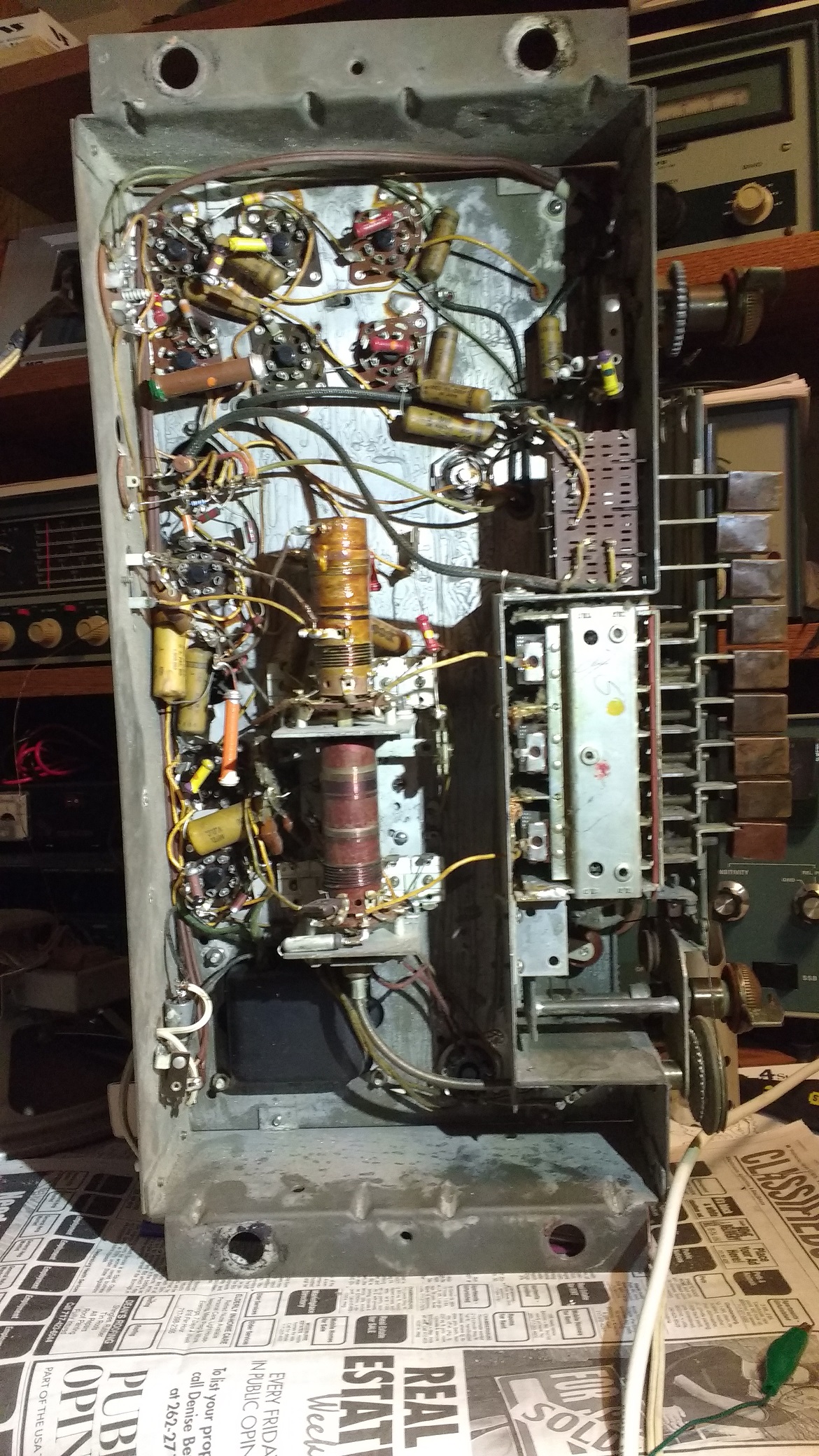
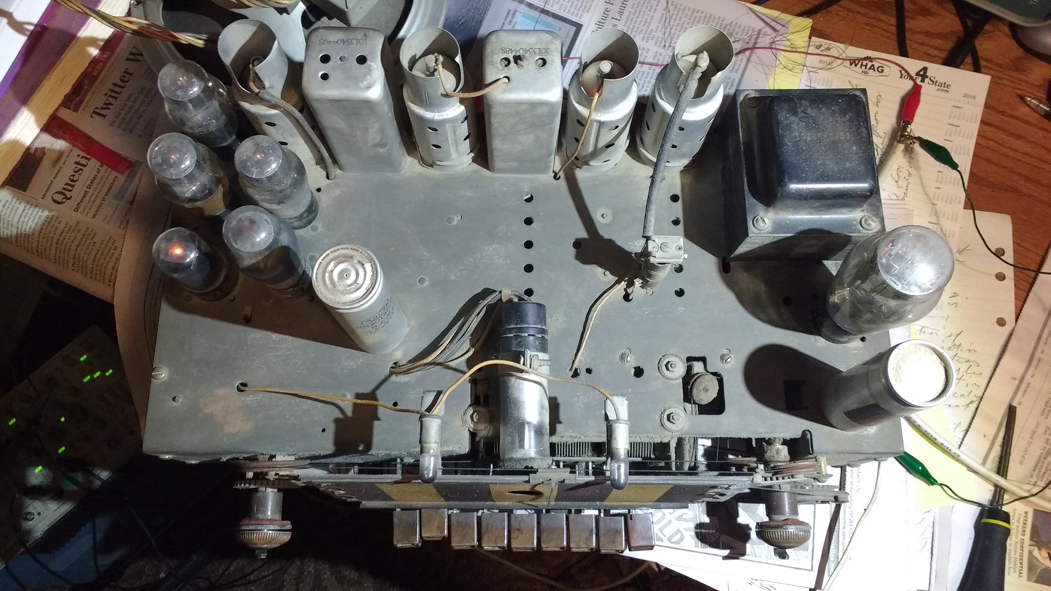
The underside of the chassis shows a similar unusual situation with the ganged band switches and RF tuning coils – the band switches (2 thin white wafers in the photo) are also perpendicular to the front panel like the tuning capacitors – for the band switches, the cable near the bottom of the photo makes a 90 degree turn to accommodate this design – it is similar to a bicycle handbrake cable with an outer shield and a flexible inner cable, and it translates turning the band switch by 90 degrees – another unusual feature was a tiny doorknob battery cell used to supply a small negative bias for the detector tube’s grid with essentially zero current drain – after almost 80 years, it still supplied 0.7 volts DC or so!!