
Ham Antenna Open Control System or HAOCS is a collection of Arduino sketches, ESP32 processor PCB’s and auxiliary, remote tuning and a Bias Tee with a 2.4 GHz port PCB’s. Together, the software and PCB’s can be used to remotely control and tune single-band or multi-band dipoles or inverted vees, verticals and other antennas. All of the software and PCB’s are open source with full design details freely available for usage and modifications. The software and PCB design files are located here:
https://drive.google.com/drive/folders/1H7sNWx6dfMaDo38TYwMdHIllE1kIvpPk?usp=drive_link
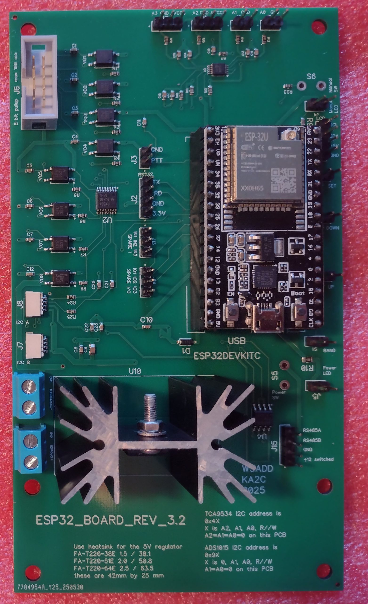
The ESP32 processor PCB can be used both in the shack as a control PCB and as a remote device PCB. It uses the ESP32 DevKitC with the ESP32-WROOM-32U module. It provides a USB interface for code downloading and Windows based user control; 8 opto-isolator relay driver outputs using a ribbon connector; two I2C connectors for external PCB’s; an U.FL RF connector for ESPNOW at 2.4 GHz for remote control over the air or over shared coax; an RS485 interface for remote control over twisted pairs; a 4-input 12-bit ADC; a LCD I2C interface; a RS-232 CAT interface; a PTT interface; pushbutton interfaces for user control and spare GPIO’s. The PCB is manufactured and mostly assembled by JLCPCB including all of the SMD components. A linear 5V regulator with a large heatsink accepts 12 VDC and provides 5VDC to the ESP32 module and PCB. A linear regulator is used to avoid switcher noise near sensitive antennas.
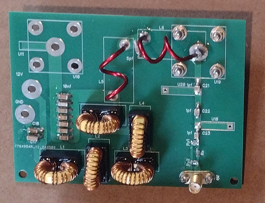
The Bias Tee with a 2.4 GHz port supports HF RF up to 1.5 kW shared with 12 VDC at up to 2.5 Amps and a 2.4 GHz control signal. This is all multiplexed onto a shared coax with a Bias Tee circuit at each end to multiplex and de-multiplex these inputs to the shared coax. A high power HF linear would attach to the UHF connector in the upper left, and the shared antenna coax would attach in the upper right. Solder pads to the left are for 12 VDC at 2.5 Amps and the SMA connector is for the 2.4 GHz ESPNOW control signal.
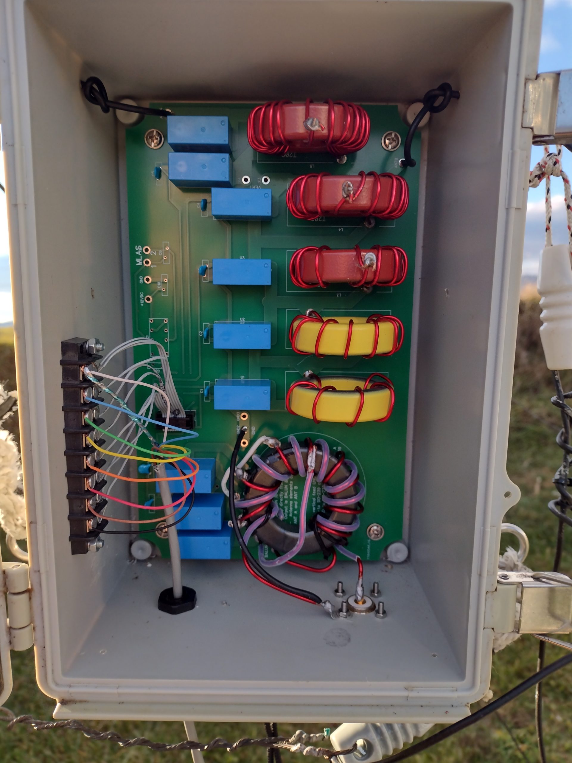
The remote High Performance Tuning PCB is shown in a weather proof box in this photo. A multimatch RF toroid transformer is at the bottom using an FT240-43 core with 3 relays to select one of 4 antenna matching impedances. There are 5 toroid inductors arranged in binary tuning steps to support 32 steps of loading. The inductive loading and the multimatch RF transformer support tuning an antenna in fine steps across the band on 160, 80 and 40 meters.
Future additions and project information will be placed at the link above on Google Drive.
The original designs for HAOCS were by Jeff Addleman, W3ADD and Nelson Sollenberger, KA2C.